2.3.5.6 Input Circuits
Seven Fixed function Input circuits are provided for
the following functions:
MODE SELECT [Auto / Manual], MANUAL TRIGGER, HOLD,
ABORT, PRESSURE MONITOR, VALVE MONITOR and FLOW
MONITOR.
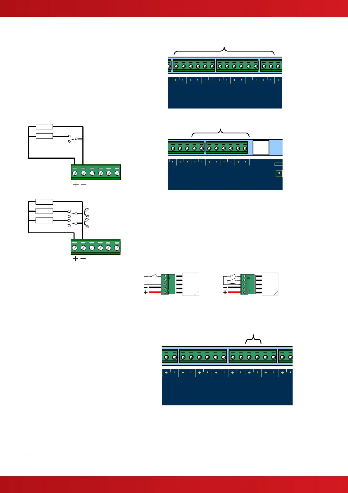
Four Programmable Function Input Circuits are
provided. Each input circuit is monitored for open
and short circuit conditions – see typical
arrangement below.
EOL = 6800Ω. Maximum line impedance 50Ω.
Connect to volt-free switches / relay contacts only.
TYPICAL SWITCH
ARRANGEMENT
VALVE FULLY OPEN (NORMAL)
VALVE MONITOR SWITCH
ARRANGEMENT
The VALVE MONITOR input is used to monitor
the open / closed state of a mechanical valve
control device.
If the valve is in an indeterminate state (neither
fully open nor fully closed) for more than 30
seconds, the panel will indicate a fault
condition.
If unused, connect a 3300Ω (or 2x 6800Ω in
parallel) EOL across the terminals.
An end-of-line module (Exp-005) is
available to simplify the wiring. This
incorporates the end-of-line resistor and
the activation resistors – see opposite.
Break off TAB to remove 6800 ohm
end-of-line resistor
Break off TAB to remove 6800 ohm
end-of-line resistor
2.3.5.7 Actuator Output Circuit
The actuator output can be used to drive both
igniting (metron) style and solenoid style
actuators.
18.0 – 28.0 V DC, 1.0A
10
SUPERVISED. POWER LIMITED.
The circuit is monitored for both open and short
circuit conditions.
The output can supply a continuous 1A current for
solenoid style actuators or can provide a 3A
(15mS) pulse for igniting style actuators.
Output type is configurable - refer to Programming
section.
TOTAL OUTPUT LOAD (continuous) must not exceed panel supply rating – maximum 2A.

 Loading...


