2.3.5.4.3 Intrinsic Safe Arrangement
7
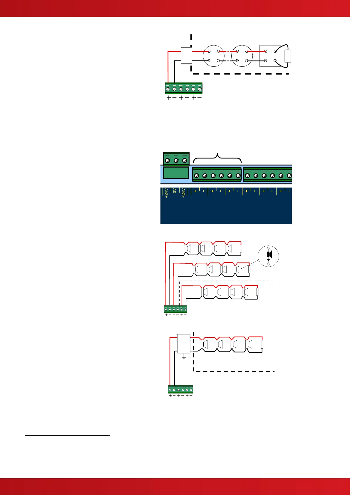
The Zone Circuit can be configured for use with
Intrinsic Safety detectors and barriers – see
programming section.
The recommended isolation barrier is a
PEPPERL+FUCHS Model: KFDO-CS-Ex1.51P or
MTL Model: 5061
Only use intrinsic safe detectors and call points.
The number of devices permitted and cables will
depend on the IS classification – refer to the
detector manufacturers’ information for further
details.
The End-of-line resistor used must be rated for the
appropriate IS zone classification.
2.3.5.5 Sounder / Monitored Output Circuits
Three conventional 24V DC sounder style output
circuits are provided.
8
18.0 – 28.0 V DC, 1.0A
9
max
SUPERVISED. POWER LIMITED.
The sounder outputs can be configured to turn on
continuously or to pulse (1s ON / 1s OFF).
The sounder outputs are monitored for open and
short circuit conditions using reverse polarity
signals.
The outputs can be configured to be non-
silencing for use with pilot valves, etc. (refer to
section 0 for programming).
Sounders must be equipped with an in-built
blocking diode that prevents the sounder from
taking power when the output is in the
supervising condition.
An End-of-Line Resistor (EOLR) of value
10,000Ω ½ Watt must be fitted to the last
sounder / bell.
Ensure that cable of appropriate conductor size is
used to maintain the required sounder operating
voltage under the minimum battery voltage
condition – see below for calculation.
GENERAL FIRE ALARM
FLOODING ZONE ALARM
2.3.5.5.1 Intrinsic Safe Arrangement
The Sounder Circuit can be configured for use
with Intrinsic Safety sounders and barriers.
The recommended isolation barrier is a MTL
Model: 778ac
Only use intrinsic safe sounders. The number of
devices permitted and cables will depend on the
IS classification – refer to the sounder
manufacturers’ information for further details.
Due to the isolation barrier internal resistance, intrinsic safe circuits are not monitored in accordance with the circuit impedance monitoring
requirements of EN54-13.
By default, SNDR1 & SNDR2 are for configured for general fire alarms. SND3 is dedicated to the extinguishant alarm (flooding zone)
output in accordance with EN12094-1.
TOTAL OUTPUT LOAD (continuous) must not exceed panel supply rating – maximum 2A.

 Loading...


