3.3.3 Extinguishing
The Extinguishing Menu comprises three separate sub-menus. These cover the operating parameters of the
actuator output (Output Set-Up), the fire alarm and manual conditions required to activate the output (Cause &
Effect) and operating parameters for any Extract output (Extract Set-Up).
[Extinguish Select]
Output Set-Up .
Cause & Effect
Extract Set-Up
Use the buttons to highlight the required menu option
and then press the button to select it.
3.3.3.1 Output Set-Up
The display presents a menu of parameter options along with their current settings.
[Release Settings]
ACTUATOR: SOLENOID .
COUNTDOWN AUTO: 0
COUNTDOWN MAN : 0
RELEASE PERIOD: 0
MINS TO RESET : 0
Use the buttons to highlight the required option and
then press the button to select it.
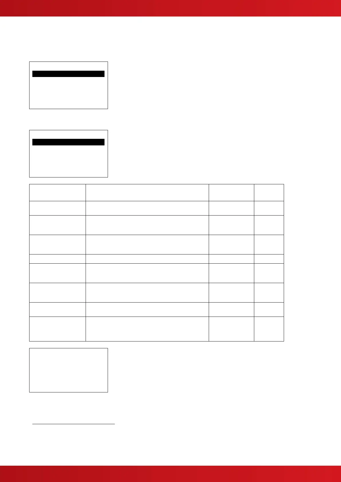
The table below details each available option.
Specifies the type of actuating devices connected to the
output.
Specifies the delay timer before activating the actuator
output when the condition originates from AFD Zone
inputs.
Specifies the delay timer before activating the actuator
output when the condition originates from any manual
trigger input.
Specifies the duration of the actuating output signal.
Specifies the minimum time that must elapse before a
reset can be performed after the activated condition has
been established.
Specifies whether the countdown time will restart or will
freeze or will continue for the remaining duration when
the hold activation is removed.
RESTART COUNT
SUSPEND COUNT
25
CONTINUE COUNT
Specifies whether a RESET can be performed during the
countdown period.
ALLOW RESET
26
PREVENT RESET
Specifies whether Flow Detection is in use. When set to
YES, the “Released” condition will not be established if
flow is not detected during the release period. The
display will also show “No flow Detected”.
[Actuator Detection]
Fault-Free Wiring?
Press √ to learn
The actuator output type must be learnt.
Press the button to proceed and the panel will analyse
the circuit to determine the type of actuating device(s).
It will also analyse the circuit impedance. No other
adjustments are necessary.
3.3.3.2 Cause and Effects Programming
The display presents a menu of parameter options along with their current settings.
This setting is not in accordance with BS EN 12094-1: 2003.
This setting is not in accordance with BS EN 12094-1: 2003.
When set to NO, the RELEASED condition is established at the instance the actuator output is turned on.
NOTE: Irrespective of the setting for this parameter, if a valid signal is received on the flow input circuit then a RELEASED condition will be
established.

 Loading...


