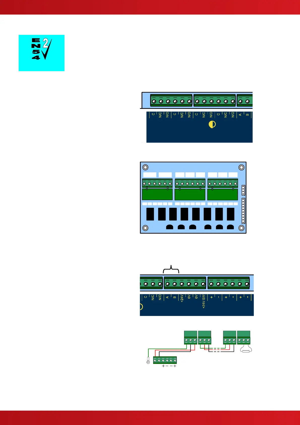
2.3.5.1 Relay Outputs
Fault Output.
The Fault Relay is arranged for failsafe operation as standard.
The panel is equipped with four relay outputs. See
diagram opposite for terminal block positions.
Each output is unsupervised with volt-free
changeover contacts rated at 30V AC/DC, 1A,
resistive.
The Fault and Fire Relays are fixed to indicate
their respective conditions.
The Fault relay is normally activated. It will de-
energise on any fault condition including total loss
of power.
Relay outputs 1&2 are programmable.
Additional Relays
If additional relays are required, then install the
Exp-008 8-Way Relay card in the rear of the
enclosure.
Mounting pillars are provided. Affix the card with
the supplied M3 fixing screws.
Connect the 10-Way ribbon cable between the
relay card and the main chassis card – the
connectors are polarised to prevent incorrect
connection.
Two changeover and six normally open volt-free
relay outputs are provided. Each is rated at 30V
AC/DC, 1A, resistive.
All Relay outputs are programmable.
2.3.5.2 RS485 Communications
One RS485 bus circuit is provided for connection
of local peripheral devices such as Remote Status
Indicator panels.
SUPERVISED. POWER LIMITED.
CCITT RS485 – Style 4
Wiring to be twisted pair and screened.
Maximum distance 1000m. Maximum line
impedance 50Ω.
Connect the cable from 'A' to 'A' and from 'B' to 'B'.
Equipment is connected via a daisy chain. A 150Ω
End-of-Line resistor to be fitted at last unit.
Connect the screen to one of the earth studs / bus
bar in the back of the panel enclosure and to the
designated point in the remote status indicator
panels. Ensure the screen is continuous.

 Loading...


