2. Hardware Functionality
See Chapter 1.2 for the product hardware overwiew. Table 1 lists a short description of the hardware,
including the links to the chapters with a detailed description.
2.1 Antennas
If the router is WiFi equipped, connect the WiFi antenna to the WiFi RP-SMA female connector on the
front panel.
Recommended tightening moment for screwing the WiFi antennas to the SMA female connectors is 0.9
Nm.
2.2 Ethernet Interfaces
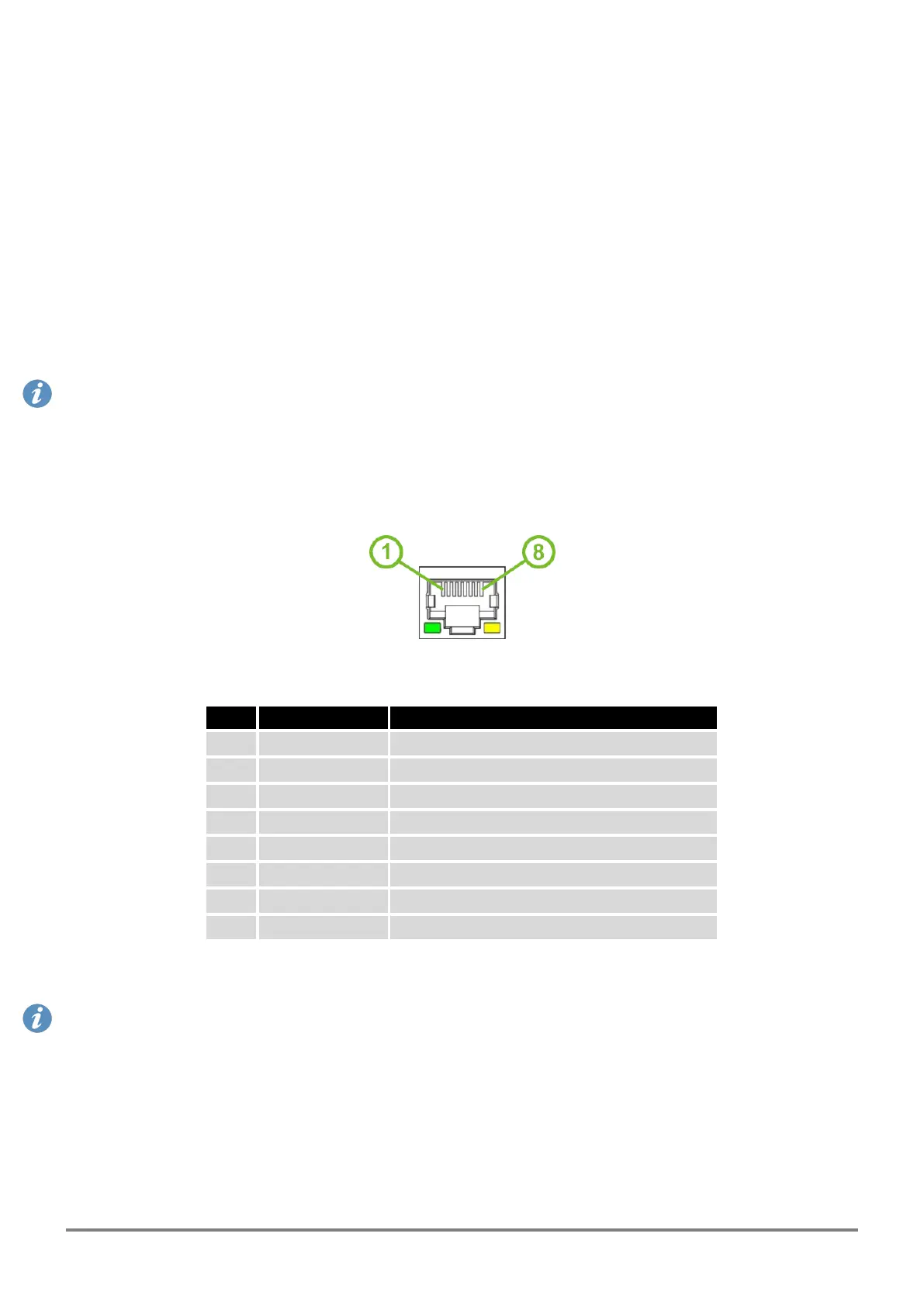
The panel socket of RJ45 is used for Ethernet interface. The pinout of the socket is shown in Figure 7
and described in Table 5.
Figure 7: Ethernet Connector Pinout
Pin Signal mark Description
1 Tx+ Transmit Data+ (positive pole)
2 Tx- Transmit Data- (negative pole)
3 Rx+ Receive Data+ (positive pole)
4 — —
5 — —
6 Rx- Receive Data- (negative pole)
7 — —
8 — —
Table 5: Ethernet Connector Pinout Description
The isolation barrier of the Ethernet ports against the ground is 1500 V.
ICR-2701 Hardware Manual (preliminary version) 11
 Loading...