1. Product Overview 1.2 Hardware Overview
1.2 Hardware Overview
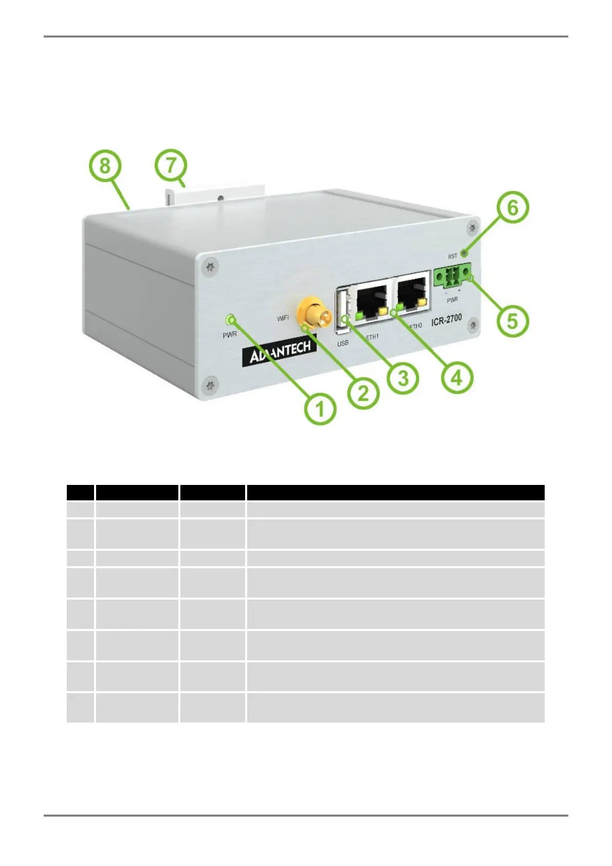
The router case preview is shown in Figure 1. A short description of hardware parts of the router is listed
in Table 1, including the links to the chapters with a detailed description. For a router in a plastic box, the
description of the components is similar.
Figure 1: Hardware Overview of the Router
# Item/Caption Type Description
1 LED - Status LED indication; see Chapter 2.6.
2 WiFi RP-SMA
female
WiFi antenna connector; see Chapter 2.1 for more infor-
mation and Chapter 4.4 for WiFi parameters.
3 USB USB-A USB-A type socket connector; see Chapter 2.5.
4 ETH0, ETH1 RJ45 100 MB Ethernet connection for the firts and second LAN;
see Chapter 2.2.
5 PWR 2-pin
terminal
Power supply socket; see Chapter 2.3.
6 RST - Button to reboot the router or to restore the default
configuration; see Chapter 2.7.
7 DIN clip - DIN rail clip, included as standard accessories; see Chap-
ter 1.8.
8 Grounding
screw
M3 Pay attention to proper grounding of model with metal box;
see Chapter 2.3.
Table 1: Hardware Overview of the Router
ICR-2701 Hardware Manual (preliminary version) 2
 Loading...