2. Hardware Functionality 2.5 USB Port
USB Socket Pinouts
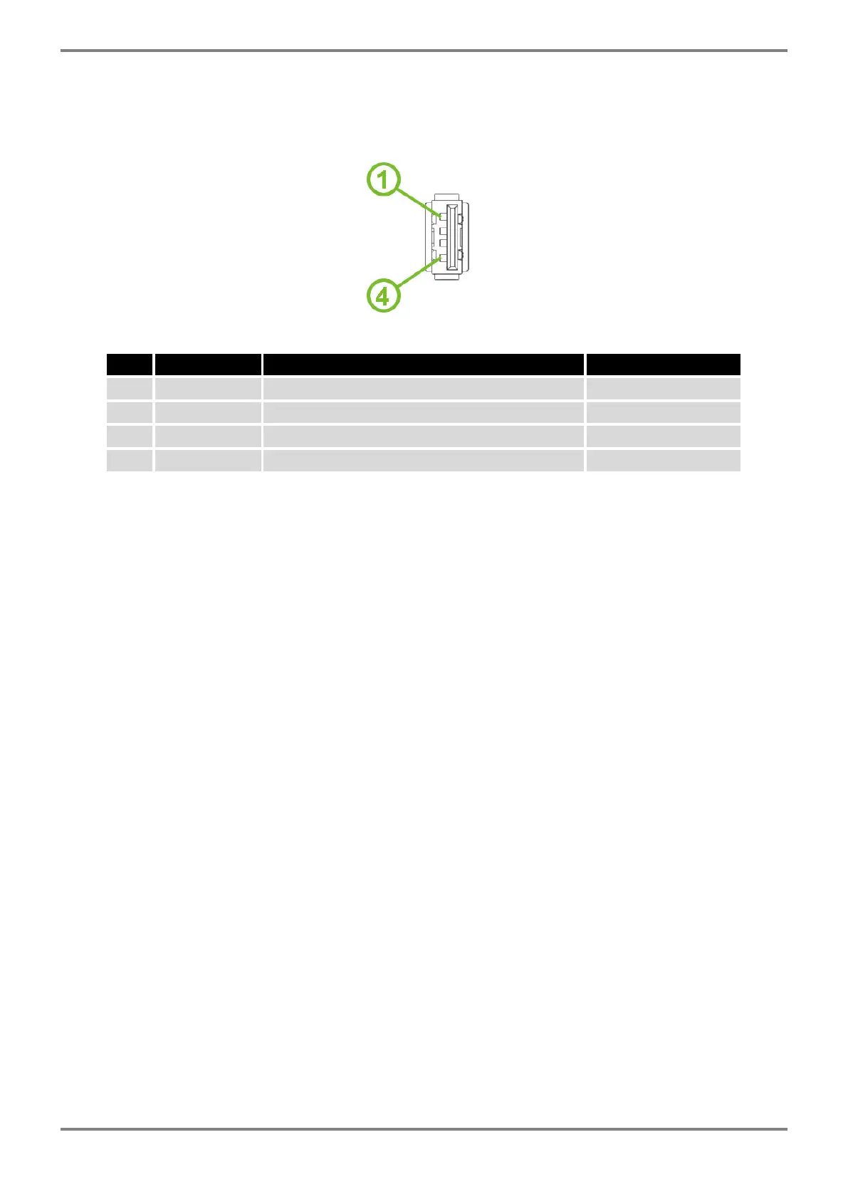
The USB socket pinouts are described in Figure 10 and Table 7.
Figure 10: USB Connector Pinout
Pin Signal mark Description Data flow direction
1 +5 V Positive pole of 5 V DC supply voltage, 0.5 A
2 USB data - USB data signal – negative pole Input/Output
3 USB data + USB data signal – positive pole Input/Output
4 GND Negative pole of DC supply voltage
Table 7: USB Connector Pinout
ICR-2701 Hardware Manual (preliminary version) 14
 Loading...