PCI-1756 User Manual 22
3.3.1 I/O Connector Pin Definition
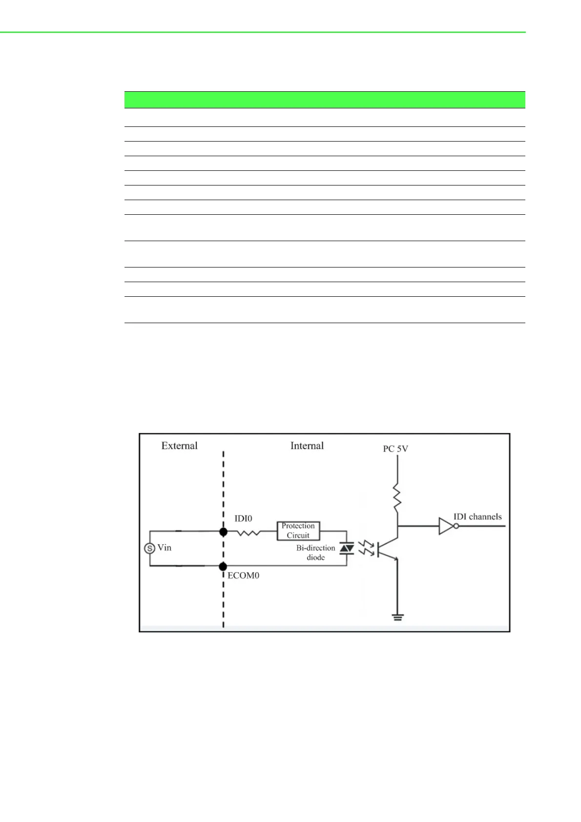
3.3.2 Isolated Digital Input
Each of isolated digital input channels accepts bi-directional 10 ~ 50 V
DC
voltage
inputs. Meaning that you can apply positive or negative voltage to an isolated input
pin (V
IN
). Every 16 input channels share one common pin. Figure 3.3 shows how to
connect an external input source to one of the card’s isolated input channels.
Figure 3.3 Isolated Digital Input Connection
Table 3.4: I/O Connector Signal Descriptions
Pin Name Reference Direction Description
IDI<00 ~ 15> ECOM0 Input Isolated digital input of group 0
IDI<16 ~ 31> ECOM1 Input Isolated digital input of group 1
IDO<00 ~ 15> PCOM0 Output Isolated digital output of group 0
IDO<16 ~ 31> PCOM1 Output Isolated digital output of group 1
ECOM0 - Input Common pin for IDI00~IDI15
ECOM1 - Input Common pin for IDI16~IDI31
PCOM0 - Output Common pin of IDO00~IDO15 for
inductive loads
PCOM1 - Output Common pin of IDO16~IDO31 for
inductive loads
IGND - - Isolated ground
CH_FRZ_IN CH_FRZ_COM Input Channel-Freeze function input pin
CH_FRZ_COM - Input Common pin for Channel-Freeze
function input