Do you have a question about the Advantech PCA-684 and is the answer not in the manual?
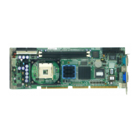
Overview of the PCA-6184 series industrial single board computer.
Key features and capabilities of the PCA-6184 CPU card.
Detailed technical specifications of the PCA-6184 board and its components.
System specifications including CPU, BIOS, and chipset.
Memory support details, including RAM type and capacity.
Specifications for I/O interfaces like parallel, serial, and keyboard/mouse.
Details on the onboard VGA controller and display memory.
Specifications for the onboard Ethernet controllers.
Specific features designed for industrial applications, like watchdog timer.
Physical dimensions, weight, and operating environmental limits.
Lists and describes the board's jumpers and external connectors.
Visual guide to the physical placement of jumpers and connectors on the board.
Important safety guidelines to follow when handling and installing the hardware.
Instructions for configuring the card using jumpers and default settings.
Explains the process of setting jumpers by connecting pins with clips.
Procedure for clearing CMOS data using the J1 jumper.
Configuration options for the watchdog timer output via J2.
Information about the PCA-6184's system memory (DIMM sockets).
Additional details and notes regarding DIMM compatibility and ECC.
Step-by-step guide for installing DIMM memory modules.
Explanation of the CPU's embedded cache memory.
Instructions for installing the CPU onto the socket.
Guidance on using the auxiliary power connector for the CPU.
How to connect IDE hard drives using CN1 and CN2.
Connecting floppy disk drives using the CN3 connector.
Connecting printers or other devices via the parallel port.
Information on connecting USB devices using the CN6 connector.
Details for connecting displays to the onboard VGA port.
Connecting network cables to the Ethernet ports.
Connecting serial devices using COM1 and COM2 ports.
Connecting keyboards and mice via PS/2 connectors.
Details on the external keyboard connector.
Information on connecting an infrared module.
Connecting the CPU cooling fan.
Connecting front panel indicators and switches.
Connecting power LEDs and keyboard lock.
Connecting an external speaker or using the onboard buzzer.
Connecting the reset button.
Connecting the Hard Disk Drive activity LED.
Connector for System Management Bus.
Guide to connecting for remote management.
Connecting ATX power supply features and soft power switch.
Details on enabling ATX soft power switch functionality.
Introduction to the Award BIOS setup utility.
Procedure for accessing the BIOS setup menu.
Configuring basic system settings like date, time, and drives.
How CMOS data is backed up and restored.
Advanced settings for system performance and boot options.
Configuration options for memory timings and chipset features.
Settings for onboard peripherals like IDE, USB, and serial ports.
Options for managing system power consumption.
Settings for Plug and Play and PCI bus configurations.
Monitoring system voltages, temperatures, and fan speeds.
Loading default BIOS settings for reliable operation.
Setting a system password for security.
Saving configured settings and exiting the BIOS setup.
Exiting the BIOS setup without saving changes.
Prerequisites and preparation for installing chipset drivers.
Explains the purpose of the Intel Chipset Software Installation utility.
Step-by-step guide for installing the Chipset Software Installation utility.
Prerequisites for installing AGP SVGA drivers.
Features of the onboard ATI Rage 128 PRO 4XL graphics accelerator.
Instructions for installing the VGA drivers from the CD.
Introduction to the PCA-6184's dual Ethernet LAN interface.
Key features of the Intel 82559 Ethernet LAN controllers.
General information on installing LAN drivers.
Step-by-step installation for Windows NT LAN drivers.
Step-by-step installation for Windows 2000 LAN drivers.
Introduction to Onboard Security (OBS) functions.
Installing OBS drivers for Windows 9X.
Installing OBS drivers for Windows NT.
How to use the utility for monitoring system hardware.
Introduction to the Ultra ATA storage driver.
Features of the Ultra ATA storage driver for enhanced performance.
Instructions for installing the Ultra ATA storage driver.
How to view driver and subsystem information.
Detailed guide on programming the watchdog timer.
Overview of the watchdog timer's functionality and purpose.
Selecting reset or interrupt behavior for the watchdog timer.
Technical details on programming the watchdog timer via I/O ports.
Provides example code for programming the watchdog timer.
Pin assignments for IDE hard drive connectors.
Pin assignments for the floppy drive connector.
Pin assignments for the parallel port connector.
Pin assignments for USB connectors.
Pin assignments for the VGA connector.
Pin assignments for Ethernet connectors.
Pin assignments for serial ports.
Pin assignments for keyboard and mouse connectors.
Pin assignments for the external keyboard connector.
Pin assignments for the IR connector.
Pin assignments for the CPU fan power connector.
Pin assignments for power LED and keyboard lock.
Pin assignments for the external speaker connector.
Pin assignments for the reset connector.
Pin assignments for the HDD LED connector.
Pin assignments for the ATX feature connector.
Pin assignments for the ATX soft power switch.
Pin assignments for extension I/O board connector CN27.
Pin assignments for extension I/O board connector CN28.
Pin assignments for the SM Bus connector.
Table of system I/O port addresses and devices.
Table detailing DMA channel assignments.
Table detailing interrupt assignments for ISA and PCI.
Memory map for the first megabyte.
Map of PCI bus functions, selections, IRQs, and grants.
| Chipset | Intel 945GME + ICH7M |
|---|---|
| Memory | Up to 2GB DDR2 |
| FDD | 1 |
| Serial Ports | 2 x RS-232 |
| Parallel Port | One parallel port supports SPP/EPP/ECP mode |
| Operating Temperature | 0°C to 60°C |
| Dimensions | 122 mm |
| Power Supply | +5V, +12V |
| Storage Temperature | -20 ~ 80° C (-4 ~ 176° F) |