EasyManua.ls Logo

Advent Controls A5 User Manual

Default Icon
28 pages
To Next Page IconTo Next Page
To Previous Page IconTo Previous Page
Page #11 background image
3.3 Signal Strength Indicator
When setting up the system it is important to know the strength of signal for reliable opera-
tion. To receive a message showing the Received Signal Strength Indicator (RSSI) the CSQ
command is sent to the system as follows:
CSQ
When the system SIM card has sufficient credit a SMS text message is sent to the number
which sent the command displaying the current RSSI.
e.g. >RSSI 21
It is recommended that the minimum signal level for the installation is 12 (-83dBm) to en-
sure reliable operation. The system will operate below 8 (–100dBm) but may become
unresponsive at times.
The CSQ command will respond to any number that sends it not just master numbers.
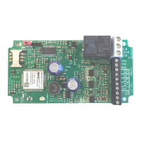
To achieve an improved RSSI the standard antenna can be upgraded to a model with
higher gain and/or the antenna should be positioned in an area with less physical ob-
struction. An extension lead can be attached to the SMA connector on the PCB to lo-
cate the antenna away from the control unit housing.
Mobile Network
Inactivity Period (With No Chargeable Events)
For Account Termination For Expiry of Unused Credit
EE
180 days 180 days
giffgaff
6 months 6 months
O2
6 months 6 months
Orange
6 months 6 months
Talkmobile
180 days 270 days
Tesco Mobile
6 months 6 months
Three
6 months 6 months
T-Mobile
180 days 180 days
Virgin Mobile
180 days 180 days
Vodafone
180 days 180 days
ASDA Mobile 180 days 270 days
Co-Operative Mobile
180 days 180 days
Delight Mobile
180 days 180 days
Lebara Mobile 84 days 180 days
Lycamobile
120 days 90 days
Mobile By Sainsbury’s
180 days 270 days
The People’s Operator
3 months 3 months
Vectone Mobile
180 days 180 days
Table 2: UK Network Inactivity Period

Table of Contents

Question and Answer IconNeed help?

Do you have a question about the Advent Controls A5 and is the answer not in the manual?

Advent Controls A5 Specifications

General IconGeneral
BrandAdvent Controls
ModelA5
CategoryGSM/GPRS Modules
LanguageEnglish

Summary

Operation

Registration

Guides on inserting and registering the SIM card for system operation.

Command Message Format

Outlines the structure and syntax for sending SMS commands to the system.

Master Number Setup

Instructions for configuring the initial master phone number for system control.

General Setup

Signal Strength Indicator

Command to check the GSM signal strength (RSSI) for optimal placement.

Relay Operation/Access Control

Enabling Any Number and Disabling Open-on-Call

Settings to allow any caller to activate the relay or restrict to specific numbers.

Relay Activation Mode

Options to set relay activation to timed pulse, ring duration, or toggle mode.

Auto-dialler: Input Triggered SMS Text Message Sending and Autodialing

Enabling and Disabling Inputs

Controls for activating or deactivating autodialing and SMS sending for specific inputs.

Input Change State Level

Defining trigger conditions for inputs (e.g., open, closed, rising/falling edge).

Analogue Voltage Measurements

Setting the Upper Voltage Threshold Voltage

Configuring the maximum voltage level that triggers alerts and dialling.

Setting the Lower Voltage Threshold Voltage

Configuring the minimum voltage level that triggers alerts and dialling.

GPRS PC Connection

Specifying the Access Point Name (APN)

How to configure the GSM network's APN for GPRS connectivity.

Installation

Power Connection

Guidance on correctly connecting AC or DC power supplies to the unit.

Input Connection

Instructions for connecting external devices to the system's optically isolated inputs.

Connection to a Burglar Alarm

How to interface the system with a burglar alarm panel's output for monitoring.

Output Connection

Details on wiring the relay outputs for controlling external devices.

Related product manuals