EasyManua.ls Logo

Advent Controls A5 User Manual

Default Icon
28 pages
To Next Page IconTo Next Page
To Previous Page IconTo Previous Page
Page #27 background image
8.5 Antenna Connection
The standard antenna can be used where a good signal exists. In areas with a poor sig-
nal an external antenna is recommended connected via RG174 coaxial cable. The sys-
tem antenna connection is a male Hirose U.FL connector. The supplied pigtail is a U.FL
female to SMA female connector. It is not recommended to use an extension greater
than 3m in length.
8.6 Mounting
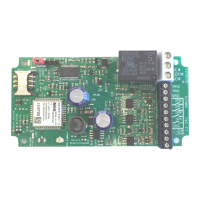
The PCB has been designed to fit into a Hammond 1591B enclosure. When mounting the
unit into such an enclosure the enclosure must be modified to allow for the antenna/
coaxial cable to be connected. When mounting in a metal cabinet, an external an-
tenna must be used, connected using 50ohm impedance coaxial cable. If required,
please contact
support@adventcontrols.co.uk for assistance.
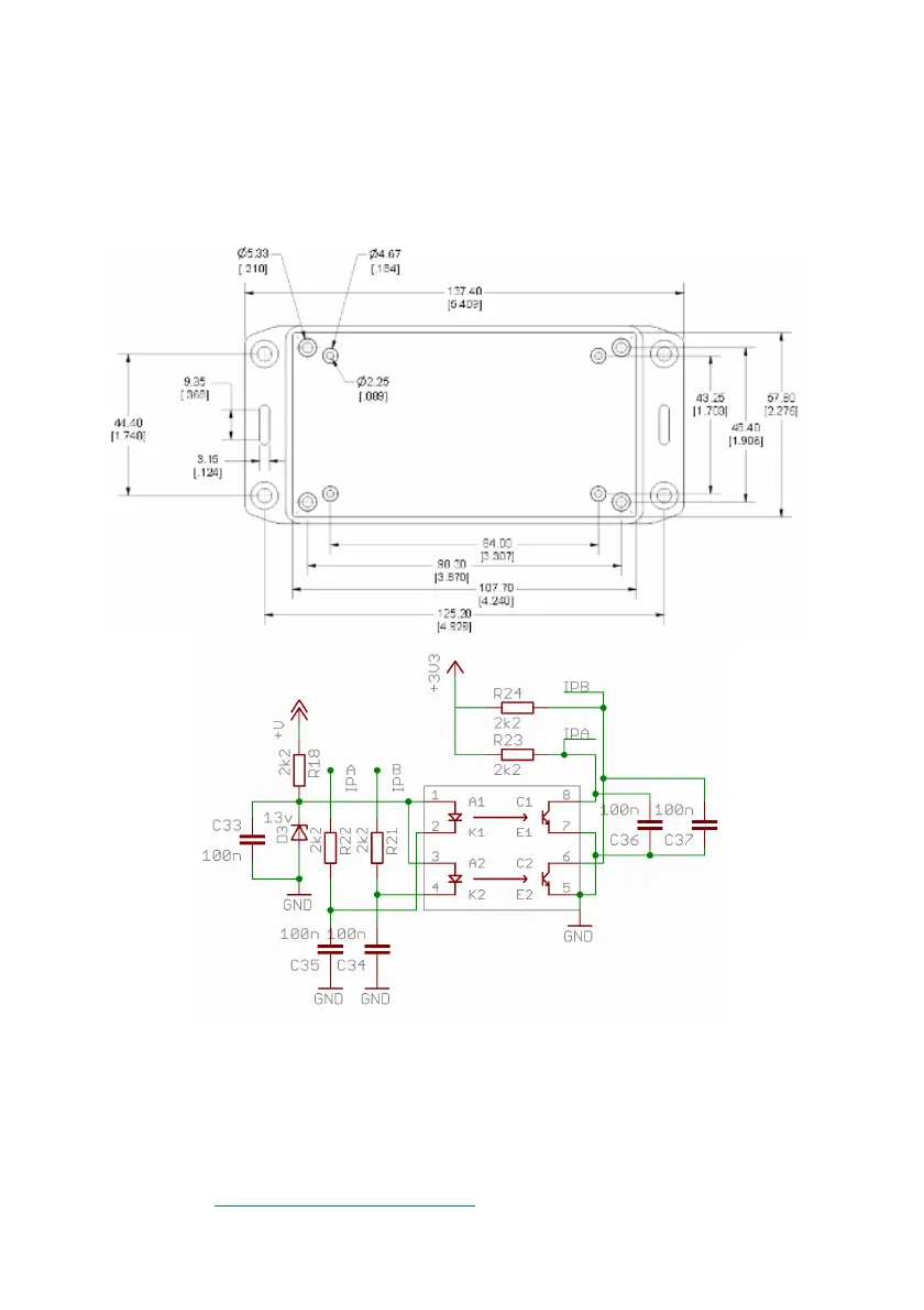
Input Circuit Reference Schematic

Table of Contents

Question and Answer IconNeed help?

Do you have a question about the Advent Controls A5 and is the answer not in the manual?

Advent Controls A5 Specifications

General IconGeneral
BrandAdvent Controls
ModelA5
CategoryGSM/GPRS Modules
LanguageEnglish

Summary

Operation

Registration

Guides on inserting and registering the SIM card for system operation.

Command Message Format

Outlines the structure and syntax for sending SMS commands to the system.

Master Number Setup

Instructions for configuring the initial master phone number for system control.

General Setup

Signal Strength Indicator

Command to check the GSM signal strength (RSSI) for optimal placement.

Relay Operation/Access Control

Enabling Any Number and Disabling Open-on-Call

Settings to allow any caller to activate the relay or restrict to specific numbers.

Relay Activation Mode

Options to set relay activation to timed pulse, ring duration, or toggle mode.

Auto-dialler: Input Triggered SMS Text Message Sending and Autodialing

Enabling and Disabling Inputs

Controls for activating or deactivating autodialing and SMS sending for specific inputs.

Input Change State Level

Defining trigger conditions for inputs (e.g., open, closed, rising/falling edge).

Analogue Voltage Measurements

Setting the Upper Voltage Threshold Voltage

Configuring the maximum voltage level that triggers alerts and dialling.

Setting the Lower Voltage Threshold Voltage

Configuring the minimum voltage level that triggers alerts and dialling.

GPRS PC Connection

Specifying the Access Point Name (APN)

How to configure the GSM network's APN for GPRS connectivity.

Installation

Power Connection

Guidance on correctly connecting AC or DC power supplies to the unit.

Input Connection

Instructions for connecting external devices to the system's optically isolated inputs.

Connection to a Burglar Alarm

How to interface the system with a burglar alarm panel's output for monitoring.

Output Connection

Details on wiring the relay outputs for controlling external devices.

Related product manuals