1. Introduction
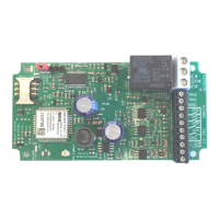
The Advent Controls X5 Series of GSM Alarm Dialler and SMS Sender Relay Boards allow for
remote monitoring and control of electronic equipment. Primarily designed for security appli-
cations these systems are ideal for use in burglar and fire alarm panels.
Digital inputs can be directly connected to open collector transistor outputs as typically found
in burglar alarm panels. They can also be connected to volt-free relay contacts, typically
found in fire alarm panels whether Normally Open (NO) or Normally Closed (NC). Dialing is
started and SMS messages can be sent when the input is driven either high, low or both.
Analogue inputs can measure voltages between 0V and 36VDC. An upper voltage for each
input can be set above which an SMS message will be sent and dialing can commence. Simi-
larly a lower threshold voltage can also be set below which SMS sending and dialing will com-
mence.
The relay can be activated by a call or SMS text from either registered telephone numbers or
can be configured to activate when receiving a call from any number. By default the call will
not be answered and hence costs the caller nothing. However, the system can also be set to
reject the call or connect a call.
Setup and operation is performed by simple SMS text messages including adding and remov-
ing user telephone numbers. A complete list of accepted telephone numbers can be viewed
via SMS text message. The memory can also be scanned to see if it contains an individual
number and the result is displayed by the on-board LED and by SMS text message. SIM card
balance checking can also be achieved using the SMS and Service data forwarding func-
tions.
The output relay has both Normally Open (NO) and Normally Closed (NC) with Common
(COM) connections. The action of the relay can be a single timed actuation from either 1s to
999s or 1 to 999 minutes or the relay can be set to toggle between calls.
Setup can also be performed over the internet on GPRS enabled devices using PC software
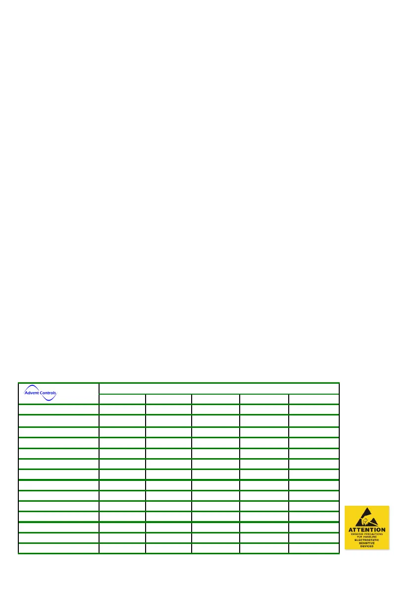
1.1 Product Selection and Specification
PCB
PCBPCB
PCB
A3
A3A3
A3 A5
A5A5
A5 B3
B3B3
B3 C4
C4C4
C4 D4
D4D4
D4
Max Numbers
Max NumbersMax Numbers
Max Numbers 384 64 512 512 512
Digital Inputs
Digital InputsDigital Inputs
Digital Inputs 2 2 1 2 4
Analogue Inputs
Analogue InputsAnalogue Inputs
Analogue Inputs 0 0 0 0 2
Output Relays
Output RelaysOutput Relays
Output Relays 1 1 2 2 1
Bluetooth Classic
Bluetooth ClassicBluetooth Classic
Bluetooth Classic No No Option Option Option
SIM Size
SIM SizeSIM Size
SIM Size Std (Mini) Std (Mini) Nano Micro Micro
GPRS Interface
GPRS InterfaceGPRS Interface
GPRS Interface No Yes Yes Yes Yes
Battery Monitoring
Battery MonitoringBattery Monitoring
Battery Monitoring No No No Yes Yes
Supply Voltage DC
Supply Voltage DCSupply Voltage DC
Supply Voltage DC 12-28V 12-28V 12-32V 12-32V 12-32V
Supply Voltage AC
Supply Voltage ACSupply Voltage AC
Supply Voltage AC 10-24V 10-24V 9-26V 9-26V 9-26V
Idle Current
Idle CurrentIdle Current
Idle Current
50mA
50mA 10-25mA 10-25mA 10-25mA
Current Max
Current MaxCurrent Max
Current Max
200mA
200mA 160mA 160mA 160mA
Antenna
AntennaAntenna
Antenna U.FL U.FL U.FL U.FL U.FL
Table 1. PCB Selection Guide
Table 1. PCB Selection GuideTable 1. PCB Selection Guide
Table 1. PCB Selection Guide