8 Installation
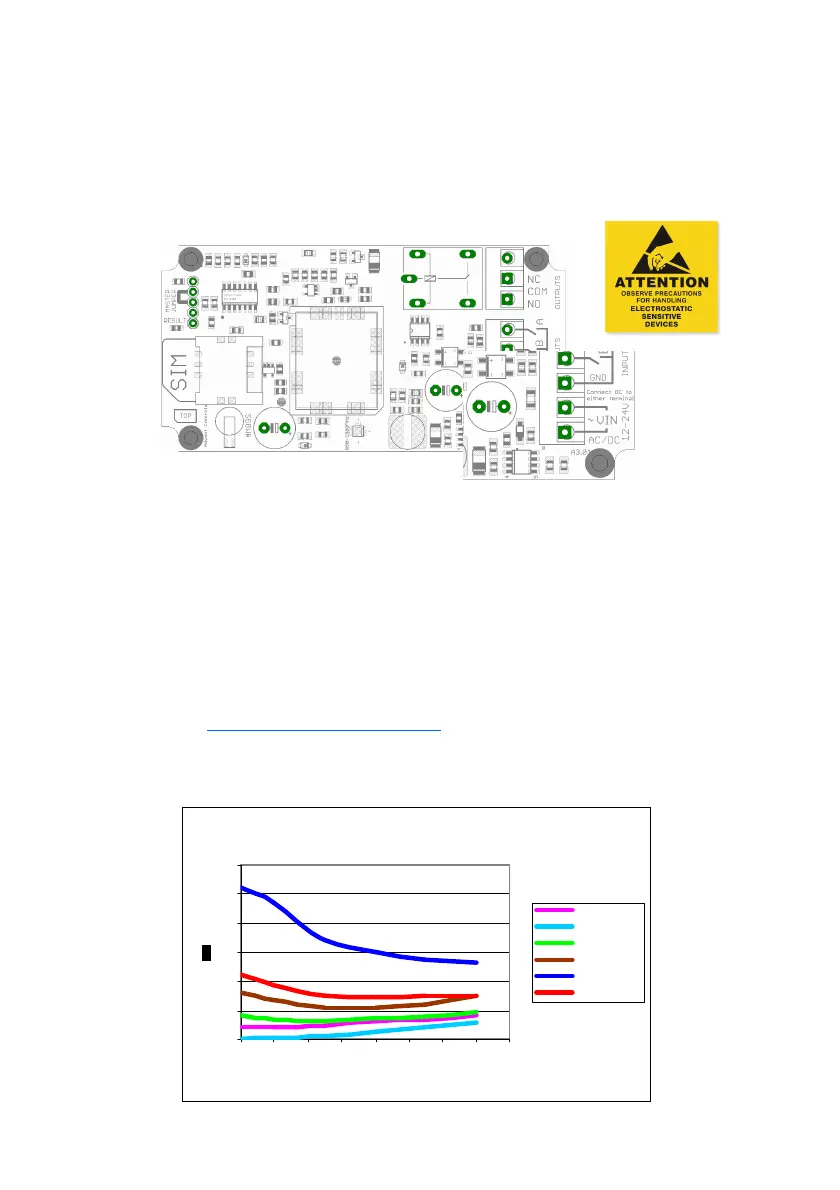
8.1 Power Connection
A fused AC or DC power supply of between 12 and 24V (MAX!) should be used with
this unit. AC voltages over 27VAC will cause the on board thermal fuse to trip and
may cause erratic operation. We recommend you measure the supply voltage
when using AC to ensure it does not exceed this voltage during normal operation.
AC power supplies should be connected to either of the ~VIN terminals. Similarly DC
supplies should be connected to these terminals with the polarity connected either
way around (i.e. +ve and –ve connected to either of the ~VIN terminals).
If DC supply voltages are liable to drop below 12VDC or it is mandatory that the
GND terminal be at the same voltage level as the supply ground, connect the nega-
tive (0v) supply to the GND terminal and the supply +ve to the outer-most ~VIN termi-
nal (terminal number 5). This will bypass the bridge rectifier for the GND negative
supply.
Please note if using this equipment in a motor vehicle please consult Advent Controls
prior to fitting (support@adventcontrols.co.uk)
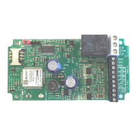
Current Consumption 1.8GHz (RSSI 9)
D 4 .0 1 C urrent C o nsumpt io n
0
20
40
60
80
100
120
10 12 14 16 18 20 22 24 26
V ol t s
Idle SMPS On DC
Sleep SMPS Of f
Idle GSM on
In call
Peak with Relay
Wi th r elay Idle