22
Interface / Battery Voltage Test
1
2
3
4
5
6
7
8
9
10
11
Fig. 1:
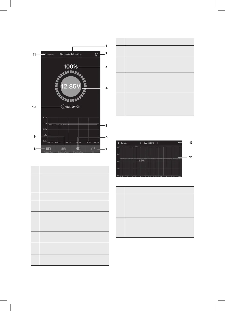
No. Function
1
name.
You can assign a device name in the Device
Manager under System Settings (2).
2 System Settings icon, tap to open settings.
3
Battery charge in % whilst not charging.
The ring will rotate during charging.
4
Shows the actual battery voltage
> 12.7 V = battery fully charged
12.4 V to 12.7 V = battery ok
< 12.4 V = low voltage.
5
Shows the battery voltage graph.
Tap the curve chart to view each individual day.
6
system, for manually testing the charging system.
7
time, stop time, and trip times for the vehicle.
No. Function
8
-
age, preset to primary interface.
9
Symbol for testing the cranking system, the
cranking system will automatically be tested
every time the engine is started.
10
Battery status
Blue = battery ok, charging status
Orange = charge soon
Red = low voltage
11
Blue = connected
Red = disconnected
After loading the settings it will automatically
restore the last connection, or you can connect or
disconnect manuall.
Symbols (6, 7, 8, 9)
Blue = selected
Grey = not selected
Voltage Graph
Fig. 2: Voltage graph
No. Function
12
Date selection: Clicking on this will open a
calendar,
orange = voltage graph available for this day
red number: A voltage abnormality occurred on
this day
13
Voltage graph; tapping it will show a slider, with
the test time appearing above the slider, the or-
ange number below the graph shows the voltage
value during this period.
12
13
12
13