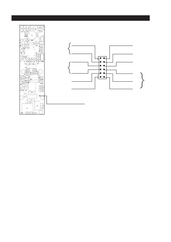
CONNECTION TERMINALS AND INDICATORS
DA-2801DA-2800
Connection Terminal
The Split-decoders (Optional)
-
AL
ARM O/P
-
KEY ACT O/P
-
N.O
.
-
COM
-
N.C.
-
N.O.
-
COM
-
N.C.
-
N.O.
-
COM
-
N.C.
-
T
AMPER
-
GND(
-
)
-
DOOR SENS
-
O/P 1 INHI
B
-
INT. LOCK
-
DU OUT
-
DOOR BELL IN
-
EG IN
-
DATA I/O
-
KEYPAD PWR
-
GND(
-
)
-
12-24V DC
OPEN COLLECTOR OUTPUT
OPEN COLLECTOR OUTPUT
1A RELAY DRY CONTACTS
FOR AUXILIARY CONTROL
1A RELAY
DRY CONTACTS
FOR AU
XILIARY CONTROL
5A RELAY
DRY CONTACTS
FOR DOOR STRIKE
OPEN COLLECTOR OUTPUT
OPEN COLLECTOR OUTPUT
INPUT/OUTPUT FOR SPLIT-DECODED SIGNALS
POWER OUTPUT FOR KEYPADS
COMMON GROUND
POWER INPUT FOR SYSTEM
N.C. SW
COMMON GROUN
N.C. SW
N.O. S
W
N.
O. SW
N.O. S
W
OUTPUT 1 OUTPUT 2 OUTPUT 3
Standard DecoderDecoder with RF Remote Control
1. GREY
2. PINK
6. BLACK
5. RED
4. ORANGE
3. PURPLE
8. BROWN
12. BLUE
11. GREEN
10. YELLOW
9. WHITE
7. LIGHT BLUE
TAMPER N.C.
OUTPUT RELAY 2
DOOR BELL
N.O.
GND (–)
12V
DC IN
(+)
N.O.
COM
N.C.
DATA I/O
(–) GND
EG IN N.O.
THE WIRE HARNESS
1 - 2 : TAMPER N.C. (Tamper Switch Normally Closed Contact)
A normally closed dry contact while the front cover is secured on the main box. It is open while the
cover is separated from the box. Connect this N.C. terminal to the 24 hour protection zone of an
alarm system if necessary.
3 - 4 : OUTPUT 2 (Door Bell N.O. Contact)
A N.O. (Normally Open) relay output dry contact with maximum rating of 24 VDC/1Amp for
activating an optional low power door bell.
5 - 6 : 12V DC (Power Input Terminal)
Connect to 12V DC power supply. The (-) GND is the common grounding points of the system.
7 : EG IN (Egress Input)
A Normally Open (N.O.) input terminal referring to (-) ground. With the help of connecting a
normally opened button to activate the Output 1 for electric door lock strike in the same manner of
using the Group 1 User PINs or Cards.
Egress button is usually put inside the house near the door. More than one egress buttons can be
connected in parallel to this terminal. Leave this terminal open if not used.
See Programming Location 90 for more information about the Egress Button with other features.
OUTPUT
RELAY
1