AEOTEC Engineering Specification
Page 8
4.6 Version
Z-Wave Protocol Library Type
Z-Wave Protocol Sub Version
ZM5101 Software Version MSB
ZM5101 Software Version LSB
Number of firmware targets
4.7 Notification
Notification Type
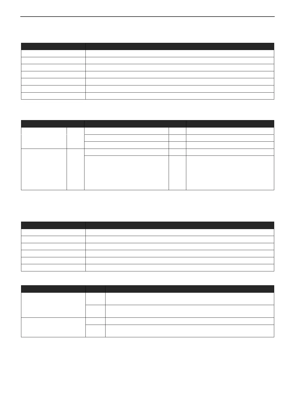
Power Management
Power is over the threshold value.
System
System hardware failure (manufacturer
proprietary failure code provided)
Event/State Parameter=0x01:
Built-in unrecoverable temperature fuse
has detected the internal temperature
exceeds the limit and disconnect. It also
means that the product has damaged if
this notification is sent out.
4.8 Protection
4.8.1 Protection Supported Report
Local Protection State Byte 1
Local Protection State Byte 2
RF Protection State Byte 1
RF Protection State Byte 2
4.8.2 Protection Set
Local Protection State Byte
Unprotected. The device is not protected, and may be operated normally via the
user interface.
No operation possible. It is not possible at all to control a device directly via the
user interface.
Unprotected. The device MUST accept and respond to all RF Commands.
No RF control - all runtime Commands are ignored by the device. The device
MUST still respond with status on requests.
Note:
(1) Regardless of the state of the product, when over-current or over-load detected, it will automatically TURN OFF
switch and set Local Protection State to be 2 and RF Protection State to be 1, and start red light blinking. Users can’t
manually or RF control the switch state until setting the Protection State to be unprotected through the Gateway or
Controller, even power off will still keep Protection State.