Smart Switch 7
ZW175
Important safety information.
Please re
ad this and the online guide(s) at
support.aeotec.com/ss7 carefully. Failure to follow the
recommendations set forth by Aeotec Limited may be
dangerous or cause a violation of the law. The manufacturer,
importer, distributor, and / or reseller will not be held
responsible for any loss or damage resulting from not
following any instructions in this guide or in other materials.
Smart Switch 7 is intended for indoor use in dry locations
only. Do not use in damp, moist, and / or wet locations.
Quick start.
The
following will step you through installing Smart Switch 7
and connecting it to your Z-Wave network.
1. Plug Smart Switch 7 into a power outlet; its LED will flash
blue slowly.
2. Add Smart Switch 7 to your Z-Wave network;
a. If your Z-Wave gateway supports SmartStart, Smart
Switch 7 is SmartStart enabled allowing you to
connect it to your Z-Wave gateway by scanning your
switch’s QR Code using your gateway’s app. Once
scanned, Smart Switch 7 will join your Z-Wave
network automatically within 10 minutes. Continue
from step 3.
b. Else, set your Z-Wave gateway into its ‘add device’
mode. Refer to the gateway’s manual if you are
unsure of how to perform this step.
c. Tap Smart Switch 7’s Action Button once, its blue LED
will blink.
d. If your gateway supports the Z-Wave Device Specific
Key (DSK) security protocol, enter the first 5 digits of
your switch’s DSK into your gateway’s interface when
prompted.
3. When Smart Switch 7 successfully joins your Z-Wave
network, its LED will become a solid blue colour for 2
seconds. Should its LED still flash blue, this indicates it
was unable to join your Z-Wave network; repeat the
above steps and please contact us for further support if
needed.
Smart Switch 7 is now a part of your Z-Wave home control
system. You can configure it and its automations via your
Z-Wave system; please refer to your software’s user guide
for precise instructions.
Get help & learn more.
Should you encounter any problem with Smart Switch 7, visit
support.aeotec.com/ss7 or contact our support team via
aeotec.com/contact. You can also learn more about Smart
Switch 7 features, configuration options, and technical
specifications at the link.
Gateway compatibility.
To see if this device is known to be compatible with your
Z-Wave gateway, please refer to
aeotec.com/z-wave-gateways.
Español.
Información importante de seguridad.
Por favor, lea cuidadosamente esta información y el manual en
support.aeotec.com/ss7. No cumplir las recomendaciones establecidas por
Aeotec Limited puede ser peligroso o constituir una violación a la ley. El
fabricante, importador, distribuidor y / o revendedor no será considerado
responsable por ninguna pérdida o daño que resulte de no cumplir
cualquiera de las instrucciones contenidas en este manual o en otros
materiales.
Smart Switch 7 está diseñado para su uso en espacios cerrados y secos. No
utilizar en locaciones con condiciones de humedad y / o en espacios
mojados.
Inicio rápido.
El siguiente manual le guiará en la instalación del Smart Switch 7 y su
conexión a su red Z-Wave.
1. Conecte el Smart Switch 7 a una toma de corriente; su LED parpadeará
en azul lentamente.
2. Agregue Smart Switch 7 a su red Z-Wave;
a. Si su puerta de enlace Z-Wave es compatible con SmartStart, Smart
Switch 7 está habilitado para SmartStart, lo que le permite conectarlo a
su puerta de enlace Z-Wave escaneando el código QR de su
interruptor utilizando la aplicación de su puerta de enlace. Una vez
escaneado, Smart Switch 7 se unirá a su red Z-Wave
automáticamente en 10 minutos. Continuar desde el paso 3.
b. De lo contrario, configure su puerta de enlace Z-Wave en su modo
"agregar dispositivo". Consulte el manual de la puerta de enlace si no
está seguro de cómo realizar este paso.
c. Pulse el botón de acción del Smart Switch 7 una vez, su LED azul
parpadeará.
d. Si su puerta de enlace es compatible con el protocolo de seguridad
de la clave específica del dispositivo (DSK) Z-Wave, ingrese los
primeros 5 dígitos del DSK de su conmutador en la interfaz de su
puerta de enlace cuando se le solicite.
3. Cuando Smart Switch 7 se une con éxito a su red Z-Wave, su LED se
convertirá en un color azul sólido durante 2 segundos. Si su LED aún
parpadea en azul, esto indica que no pudo unirse a su red Z-Wave; repita
los pasos anteriores y póngase en contacto con nosotros para obtener
más ayuda si es necesario.
El Smart Switch 7 ahora es parte de su sistema de control de hogar Z-Wave.
Puede configurar tanto el dispositivo como las automatizaciones a través de
su sistema Z-Wave; por favor, para obtener instrucciones más precisas
revise el manual de usuario del Software.
Français.
Informations importantes concernant la sécurité
Veuillez lire attentivement ce document et le(s) guide(s) à l'adresse
support.aeotec.com/ss7. Le non-respect des recommandations formulées
par Aeotec Limited peut être dangereux ou entraîner une violation de la loi.
Le fabricant, l'importateur, le distributeur et / ou le revendeur ne seront pas
tenus responsables de toute perte ou dommage résultant du non-respect
des instructions contenues dans ce guide ou dans d'autres documents.
Smart Switch 7 est destiné à être utilisé à l'intérieur dans des endroits secs
uniquement. Ne pas utiliser dans des endroits humides, mouillés et / ou
trempés.
Démarrage rapide.
Les étapes suivantes vous guideront dans l'installation de Smart Switch 7 et
sa connexion à votre réseau Z-Wave.
1. Branchez la Smart Switch 7 dans une prise de courant; sa barre LED
clignotera lentement en bleu.
2. Ajoutez la Smart Switch 7 à votre réseau Z-Wave ;
a. Si votre passerelle Z-Wave prend en charge SmartStart, Smart Switch
7 est activé par SmartStart, ce qui vous permet de le connecter à votre
passerelle Z-Wave en scannant le code QR de votre commutateur à
l’aide de son application. Une fois numérisé, Smart Switch 7 rejoindra
automatiquement votre réseau Z-Wave dans les 10 minutes. Continuez
à partir de l'étape 3.
b. Sinon, configurez votre passerelle Z-Wave en mode «Ajout de
périphérique». Reportez-vous au manuel de la passerelle si vous ne
savez pas comment effectuer cette étape.
c. Appuyez une fois sur le bouton d'action du commutateur intelligent 7,
son voyant bleu clignotera.
d. Si votre passerelle prend en charge le protocole de sécurité Z-Wave
Device Specific Key (DSK), entrez les 5 premiers chiffres de la clé
DSK de votre commutateur dans l'interface de votre passerelle lorsque
vous y êtes invité.
3. Lorsque la Smart Switch 7 rejoint avec succès votre réseau Z-Wave, sa
LED devient bleue fixe pendant 2 secondes. Si sa DEL clignote toujours
en bleu, cela signifie qu'il n'a pas pu rejoindre votre réseau Z-Wave ;
répétez les étapes ci-dessus et contactez-nous pour plus d'assistance si
nécessaire.
Deutsch.
Wichtige Sicherheitsinformationen.
Bitte lesen Sie dieses Dokument und die Anleitung(en) unter
support.aeotec.com/ss7 sorgfältig durch. Den festgelegten Empfehlungen
der Aeotec Limited nicht zu folgen, kann gefährlich sein oder gegen ein
Gesetz verstoßen. Der Hersteller, Importeur, Vertreiber und / oder Verkäufer
haftet nicht für den Verlust oder Schaden, der durch die Nichtbeachtung der
Vorschriften in dieser Anleitung oder in anderen Material entsteht.
Smart Switch 7 ist nur für den Innengebrauch bestimmt. Nicht in einer
dunstigen, feuchten oder nassen Umgebung verwenden.
Schnellstart.
Im Folgenden werden Sie Schritt für Schritt durch die Installation und das
Verbinden des Smart Switch 7 mit einem Z-Wave Netzwerk geführt.
1. Schließen Sie den Smart Switch 7 an eine Steckdose an; seine LED blinkt
langsam blau.
2. Hinzufügen des Smart Switch 7 zu Ihrem Z-Wave Netzwerk:
a. Wenn Ihr Z-Wave-Gateway SmartStart unterstützt, ist Smart Switch 7
für SmartStart aktiviert, sodass Sie es mit Ihrem Z-Wave-Gateway
verbinden können, indem Sie den QR-Code Ihres Switches mit der
App Ihres Gateways scannen. Nach dem Scannen wird der Smart
Switch 7 innerhalb von 10 Minuten automatisch mit Ihrem
Z-Wave-Netzwerk verbunden. Fahren Sie mit Schritt 3 fort.
b. Anderenfalls setzen Sie Ihr Z-Wave Gateway in den Modus "Gerät
hinzufügen". Lesen Sie im Handbuch des Gateways nach, wenn Sie
nicht sicher sind, wie dieser Schritt ausgeführt werden soll.
c. Tippen Sie einmal auf die Aktionstaste des Smart Switch 7, die blaue
LED blinkt.
d. Wenn Ihr Gateway das DSK-Protokoll (Device Specific Key) von
Z-Wave unterstützt, geben Sie bei Aufforderung die ersten 5 Ziffern
des DSK Ihres Switches in die Schnittstelle Ihres Gateways ein.
3. Wenn der Smart Switch 7 sich erfolgreich mit Ihrem Z-Wave Netzwerk
verbindet, leuchtet seine LED für 2 Sekunden Blau. Wenn seine LED
immer noch blau blinkt, ist die Verbindung mit Ihrem Z-Wave Netzwerk
nicht zustande gekommen. Führen Sie dann das Hinzufügen des Sensors
erneut durch. Für weitere Unterstützung kontaktieren Sie uns.
Der Smart Switch 7 ist jetzt eine Komponente Ihres Z-Wave Smart Home
Systems. Sie können das Gerät und seine Automatisierungen nun über Ihre
Z-Wave Zentrale konfigurieren. Nehmen Sie dazu bitte das Handbuch Ihrer
Z-Wave Zentrale zur Hand und folgen Sie den Anweisungen für eine
Automatisierung.
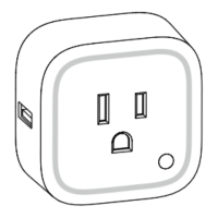
RGB LED
Action Button
Botón de acción / Bouton
d'action / Aktionsknopf / Pulsante
di azione / Actieknop /
Åtgärdsknapp / Handlingsknapp
Note:
The label of QR Code and Pin Code are
used for SmartStart Inclusion. The Z-Wave DSK
Code is at bottom of the package. Please do
not remove or damage them.
Pin Code: 35732