Page 11 of 30 AERCO International, Inc. • 100 Oritani Dr. • Blauvelt, New York 10913 • Phone: 800-526-0288 PR1 04/08/2014
Application Guide
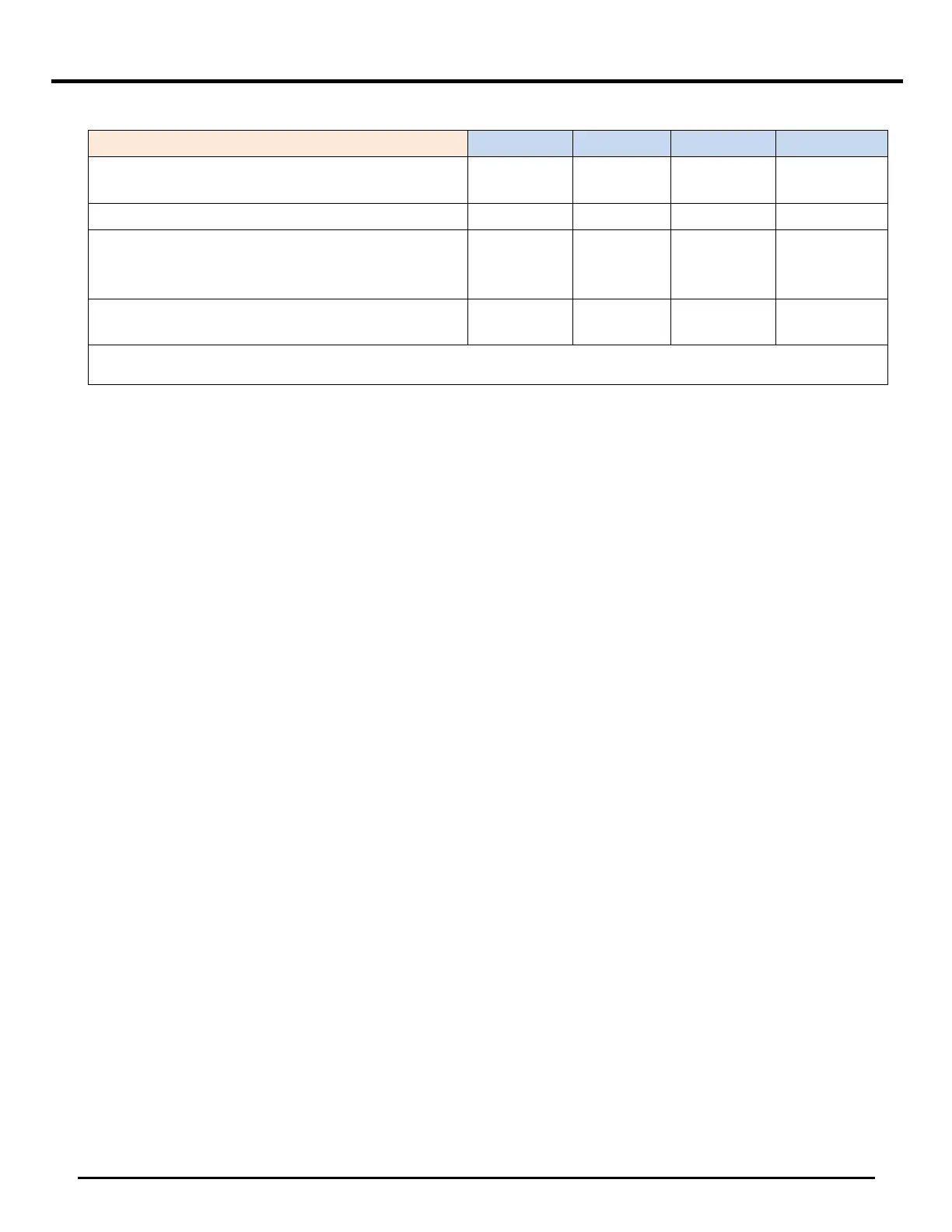
TABLE 1: Flow Rate and Pressure Drops
Strainer, Pipes, Valves and Fittings Size
1-1/4" NPT
1-1/2"
NPT
2" NPT 2" NPT
Strainer ∆P (Ft. of Hd.) – (‘Y’ Strainer, 20 mesh) 0.41 0.64 0.70 1.25
∆P (Ft. of Hd.) – (20’ SCH.40, 4 x 90°, 2 x
reducing
couplings, 2 x Ball Valve)
0.71 1.21 0.92 1.76
Total Primary Loop ∆P (Ft. of Hd.) @ ∆T of
25°F
20.12 56.85 43.13 41.01
NOTE: A reducing coupling is not used where boiler line size matches outlet size.
2.4. PRIMARY PUMP
The primary pump shall have a discharge pressure able to assure the designed water flow rate, taking
into account pressure drop losses as shown in Figure 2. When selecting a pump, take into account
the pressure drop across the unit, fittings, accessories, and piping. The primary pump electrical
connection shall be made as shown in Figure 4 for boilers and Figure 5 or 6 for water heaters (terminals 113
and 114).
Pumps shall be calculated by installers or engineers according to boiler and system parameters. The
pump is not an integral part of the boiler.
• If water is between 5 and 8 grains, water is soft, and must have a minimum velocity of 4 ft/sec.
See Table 1.
• If water is between 9 and 17 grains, water is normal, and flow should be between 4-8 ft/sec.
• If water is between 18 and 23 grains, water is hard, and must have a minimum velocity of 8
ft/sec.
NOTE
Select the pump flow rate so that the boiler water outlet temperature is
190°F (87.8°C) or below.
 Loading...