Page 18 of 30 AERCO International, Inc. • 100 Oritani Dr. • Blauvelt, New York 10913 • Phone: 800-526-0288 PR1 04/08/2014
Application Guide
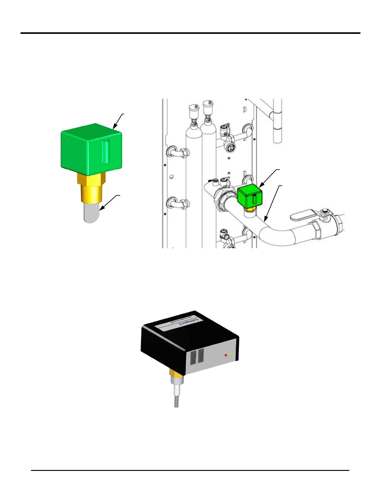
Flow Switch 2.3.5.
A flow switch is required to be installed on every unit (Figure 7). This flow switch is included with the
unit and must be field-installed.
The flow switch should be installed in a tee on the boiler outlet piping as shown in Figure 7. The
paddle of the flow switch may have to be cut to length for the given pipe diameter according to the
manufacturer’s instructions. You must NOT install any valves in between the unit and the flow switch.
Figure 7: Supplied Flow Switch (L) and Installation Location (R) Example
Low Water Cutoff (LWCO) 2.3.6.
If a low water cutoff (LWCO) is preferred (Figure 8), one may be installed in place of, or in addition to,
the flow switch. This is available as an accessory from AERCO. When installing such a device, you
must consult and abide by all local codes and regulations in force.
Figure 8: Optional Low Water Cutoff (LWCO)
NOTE
Use Teflon tape or a suitable pipe joint compound for component and
piping connections.
PIPING
SWITCH
PADDLE
SWITCH
 Loading...