CONTROL PANEL OPERATING PROCEDURES
8/1/99
the end of the trial for
ignition period.
AIR FLOW
opened after flame was
Flame signal was lost
after flame was proven.
The combustion
safeguard is locked out.
3.5.3 ANNUNCIATOR START
SEQUENCE MESSAGES
The following table lists the annunciator MAIN
display start sequence messages.
STANDBY
mode waiting for a call
The unit is in the 7-sec.
purge.
IGNITION TRIAL
ignition position,
attempting to light the
FLAME PROVEN
established flame and
3.6 THE COMBUSTION SAFEGUARD
The Combustion Safeguard is responsible for
monitoring the safety components during the
start sequence and after flame is established. It
is also responsible for the timing of the start
sequence, including the purge and ignition
cycles.
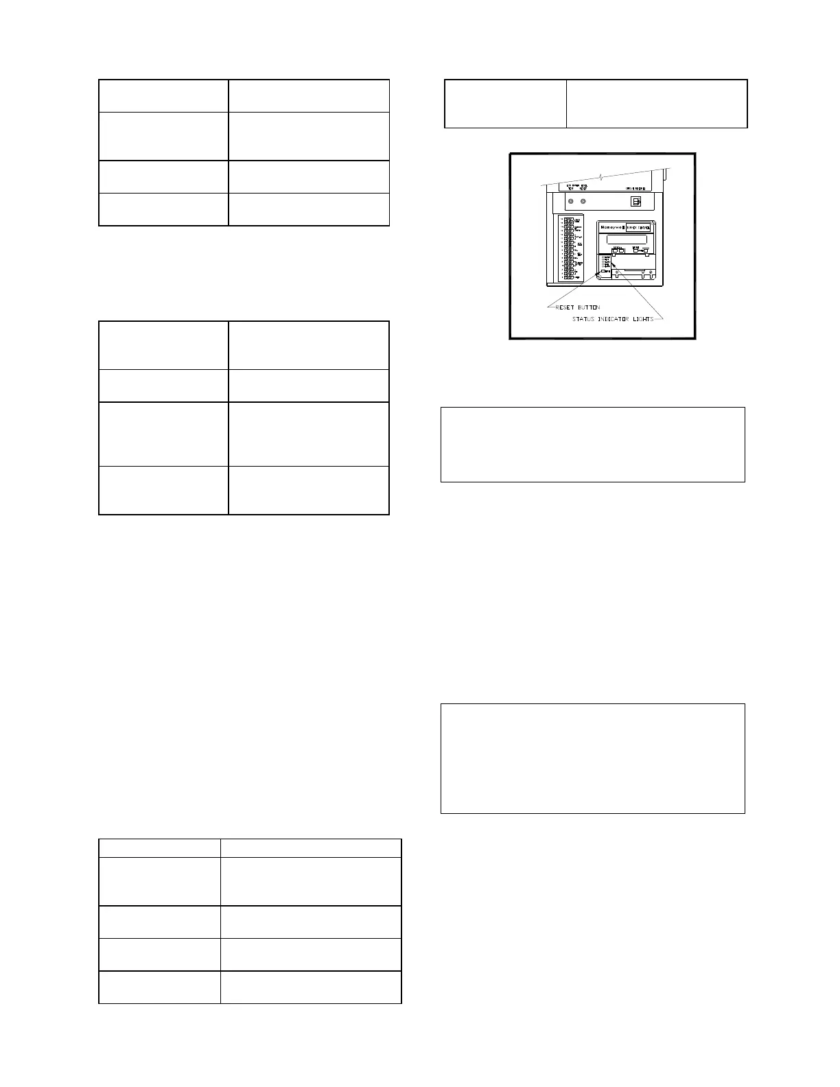
The combustion safeguard is located in the
bottom of the control panel as shown in Figure
3.9. There are five status LED’s that indicate the
status of operation. These lights are redundant
to messages displayed by the annunciator. and
are useful as a double check on the annunciator.
The table below defines the function of each
LED’s. A reset button located on the combustion
safeguard is used to reset it after a lockout. The
combustion safeguard will shut the unit down if
one of the following occurs:
POWER
Lights when the limit string
is satisfied and there is a
PILOT
Lights when the air flow
circuit is satisfied.
FLAME
Lights during the trial for
ignition period.
MAIN
Lights once flame has
been detected.
ALARM
controller is in a
3.9
Combustion Safeguard Status Indicator LED
Location
Note:
After resetting the combustion safeguard
the Annunciator must also be reset using
the CLEAR button.
3.7 WATER LEVEL TEST and RESET
SWITCHES
The water level switches are located on the left
side of the control box (see Fig. 3.10). When
depressed, the TEST switch simulates a low
water level condition by breaking the connection
between the water level probe and the sensing
circuitry. To test the low water level circuitry
depress the test switch for 3 seconds. The unit
should fault resulting in the red fault light blinking
and the LED display showing LOW WATER
LEVEL.
Note:
Only water level circuitry is tested during the
above test. The water level probe is not
tested. To determine if the probe is
functioning properly, the water level must be
reduced below the level of the probe.
To reset the unit, depress the water level reset
switch, the annunciator CLEAR button, and if
necessary, the reset button on the combustion
safeguard.
 Loading...


