CONTROL PANEL OPERATING PROCEDURES
8/1/99
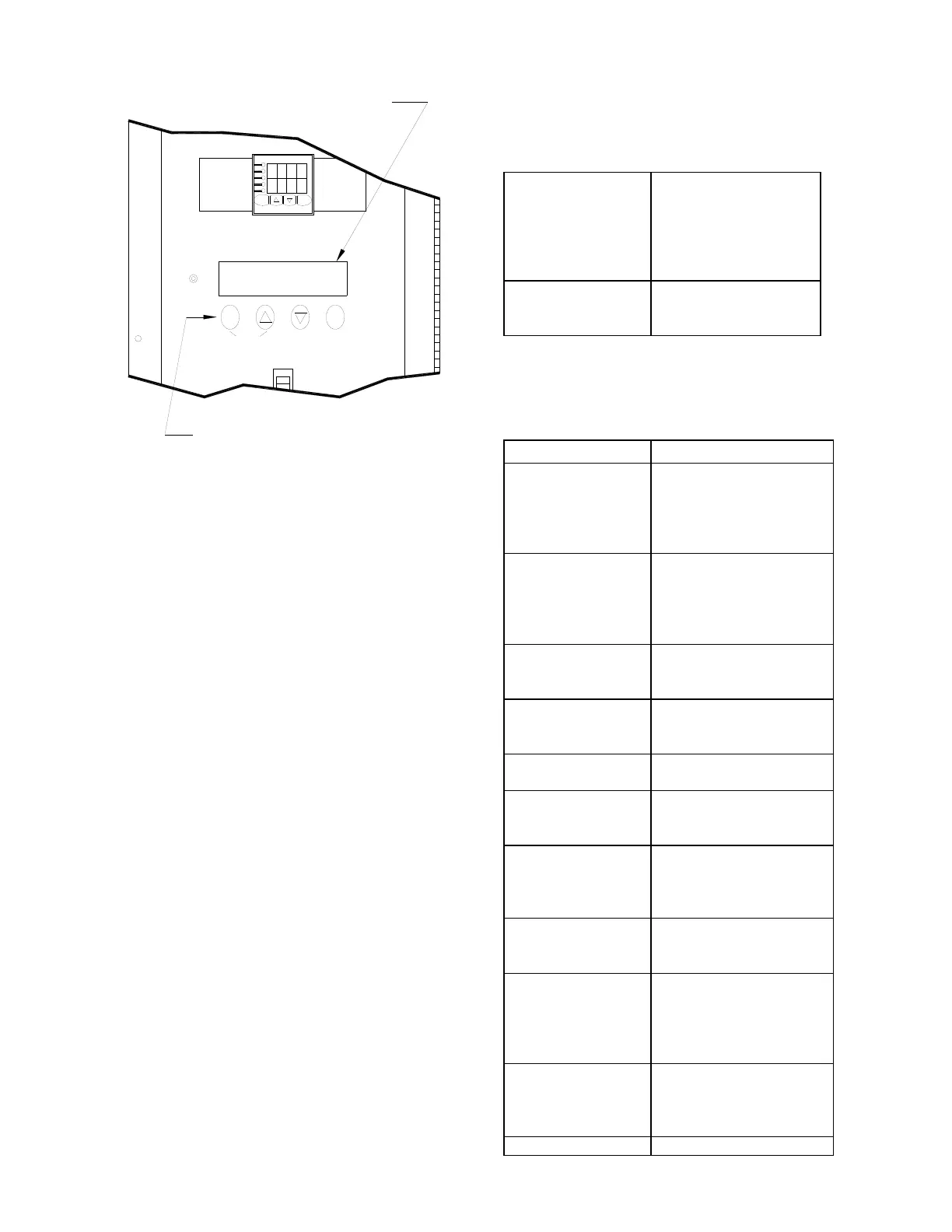
Figure 3.8
Annunciator Function Switches and LCD Display
The status annunciator only monitors the boilers
control system. If any portion should fail, the
boiler will still operate with no adverse effects.
3.5.1 ANNUNCIATOR FUNCTION
SWITCHES and DISPLAYS
The Annunciator has three function displays that
are available to the operator. These are the
MAIN, the CYCLES, and the SET DATE
displays. These displays are accessed using the
four membrane switches located directly under
the LCD display on the front of the control panel.
They are labeled CLEAR, , , and AUX.
The MAIN display is used during normal
operation of the unit. In the MAIN display, start
sequence and fault messages can viewed. To
return to the MAIN display from any other
display, simultaneously press CLEAR and the
arrow key. To reset the MAIN display after a
fault has occurred press the CLEAR button.
The CYCLES display indicates the date and
time, and the number of cycles the unit has
started since it was reset. When in the CYCLES
display only the number of cycles can be reset.
To reset the number of cycles to 0,
simultaneously press the , and arrow keys
and hold them for approximately four seconds.
In the SET DATE display, both the time and date
are displayed and can be changed.
To access the SET DATE display, press the
CLEAR button while in the CYCLES display.
Continue pressing the CLEAR button to move
through the SET DATE display fields. Use the
and arrow keys to set the date and time.
The following table shows the messages
displayed after accessing the CYCLES and SET
DATE displays.
# CYCLES =
“DATE” “TIME”
the controller has
completed it’s start
cycle, and the time
and date of the last
SET DATE:
“DATE” “TIME”
Displays and allows
setting of the date
3.5.2 ANNUNCIATOR FAULT
MESSAGES
The following table lists the Annunciator MAIN
display fault messages and their meanings.
RESET MAIN
POWER
interrupted. Power must
be shut off for 20
seconds then restored
HIGH WATER
TEMP
due to the outlet water
temperature exceeding
the high temperature
PRESSURE
due to low gas
HIGH GAS
PRESSURE
due to high gas
below the probe level.
INTERLOCK
OPEN
in the relay box, are not
PURGE INTLK
OPEN
the purge switch did not
prove closed during the
LOW AIR FLOW
not prove closed during
SYSTEM FAULT
PURGE
INTERLOCKS
The proof of closure or
purge switch did not
prove closed 45
seconds after the unit
SYSTEM FAULT
LOW AIR
did not prove closed 45
seconds after the unit
FAULT
CLEAR
AUX
MODE
ON
ANNUNCIATOR DISPLAY
ANNUNCIATOR FUNCTION SWITCHES
 Loading...


