PR1: 04/01/11 Page| 6
Modulex Fireside (24-month) Maintenance
AERCO International, Inc. • 100 Oritani Dr. • Blauvelt, New York 10913 • Phone: 800-526-0288
Technical Instruction Document
1.4.1 – Unit Disassembly for Burner Maintenance
Tools required: Phillips head screwdriver, 13mm socket wrench (with extender), and an Exacto blade (or
small sharp knife). Access to a steel brush and water jet are also recommended. See Instruction 1.4.1.
Unit Disassembly for Fireside
Inspection
1. Disconnect electrical power to the unit by
turning off the external circuit breaker.
2. Turn off the external gas supply shutoff valve.
3. Remove the top cover from the boiler. A
screwdriver may be needed to pry the cover
from the two pins on either end. The cover is
secured with spring clips and pins to the front,
back and side panels of the unit. In addition,
two (2) groups of ground wires from the frame
of the boiler are attached with clips to the
underside of the top cover. Use care when
disconnecting these ground wire clips. Note
that all lugs have capture spring clips that are
released by pressing a small nub under the
lug body.
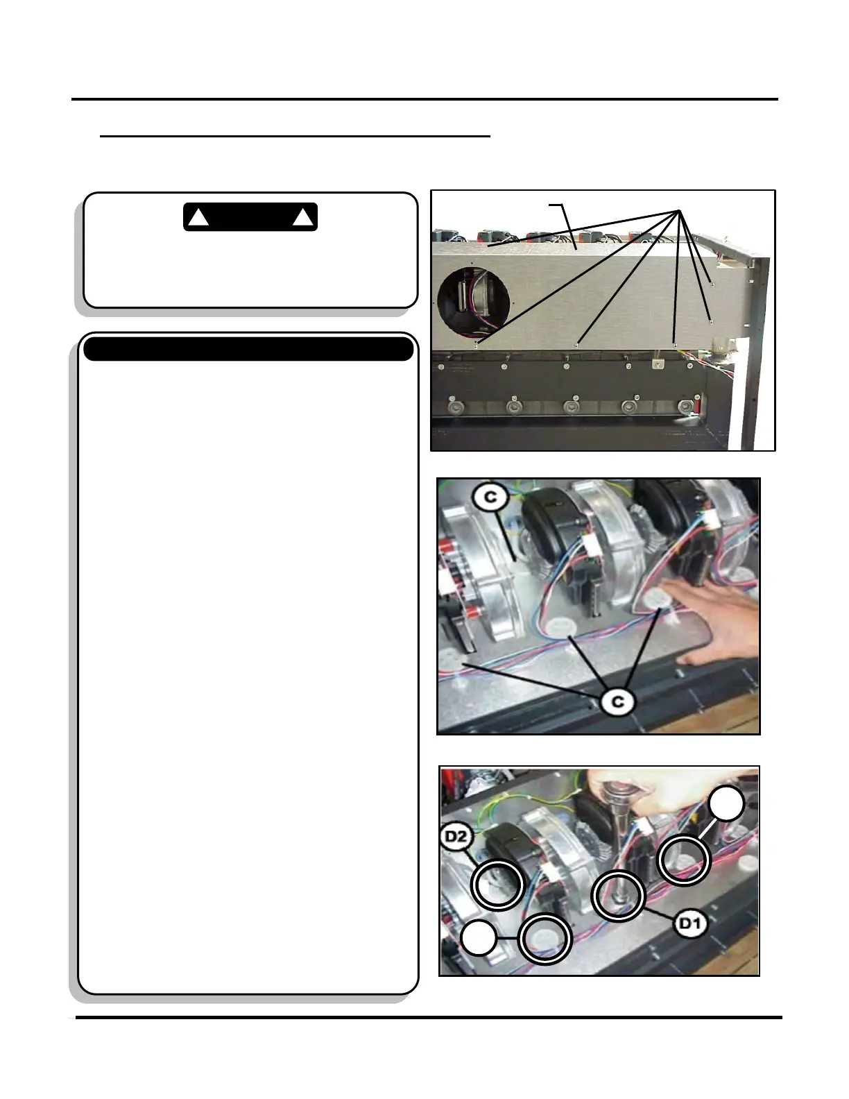
4. Remove the front panel from the boiler to
provide access to the fan assembly cover
(Figure 4).
5. Remove the screws from the various
locations on the fan assembly cover. A
sampling of screw locations is shown in
Figure 4.
6. Remove the plastic cap bolt covers (C) from
the bottom of the fan chamber to access the
bolts holding the fan assembly in place
(Figure 5).
7. Using a 13 mm socket wrench, remove the
bolts D1, D2, D3, and D4 that secure the fan
chamber cover onto the burner assembly
(Figure 6).
(Continued on Next Page)
Cover
Figure 4: Remove Fan Assy Cover
Figure 5: Remove Plastic Bolt Covers (C)
Figure 6:
Remove Plastic Bolt Covers (C)
Prior to performing the following disassembly and
inspection procedures, ensure that all electrical
power to the boiler has been turned OFF and the
external gas shut-off valve is fully CLOSED.
 Loading...