35
AE-L
COM
IA
C/F
AE-N
15V
0V
1
0
ALAR M
PR3
PANNELLO COMANDI
REMOTE CONTR OL
7 6
5 4 3
2
1
max 150m
SEZ. MIN. 0.5 mm
IA
AUSILIARIO
INTER RUTTORE
SWITCH
AUXILIARY
AE
ESTER NO
ALLARME
ALARM
REMOTE
max 150m
SEZ. MIN. 0.5 mm
CB1
ATTENZIONE!
RE F. CEI E N 60335-2-40
tutti gli altri forniscono un'isolamento rinforzato.
rispetto all'alimentazione della macchina,
I morsetti 6 e 7 forniscono un'isolamento principale
ATTENTION!
all others give a reinforced insulation.
opposed to main power supply line,
Terminals 6 and 7 provide basic insulation
3/2
3/4
3/4
3/3
3/2
2/8
2/8
3/2
3/2
3/3
3/3
M7S-5
M5S1-1
M5S1-2
M7-6
M7-5
M1S-8
M1-8
M7S-4
M7S-3
M7S-7
M7S-8
Evaporator less option (C) auxiliary connections
AE-L
COM
IA
C/F
AE-N
15V
0V
1
0
ALAR M
MAX 1A
230V
PR3
PANNELLO COMANDI
REMOTE CONTR OL
7 6
5 4 3
2
1
max 150m
SEZ. MIN. 0.5 mm
IA
AUSILIARIO
INTER RUTTORE
SWITCH
AUXILIARY
AE
ESTER NO
ALLARME
ALARM
REMOTE
max 150m
SEZ. MIN. 0.5 mm
CB1
ATTENZIONE!
RE F. CEI E N 60335-2-40
tutti gli altri forniscono un'isolamento rinforzato.
rispetto all'alimentazione della macchina,
I morsetti 6 e 7 forniscono un'isolamento principale
ATTENTION!
all others give a reinforced insulation.
opposed to main power supply line,
Terminals 6 and 7 provide basic insulation
3/2
3/4
3/4
3/3
3/2
2/8
2/8
3/2
3/2
3/3
3/3
M7S-5
M5S1-1
M5S1-2
M7-6
M7-5
M1S-8
M1-8
M7S-4
M7S-3
M7S-7
M7S-8
AE-L
COM
IA
AE-N
15V
0V
C/F
1
0
ALAR M
T T T T
MAX 1A
230V
PR3
PANNELLO COMANDI
RE MOTE CONTROL
7 6
5 4 3
2
1
max 150m
SEZ. MIN. 0.5 mm
IA
AUSILIARIO
INTERR UTTORE
SWITCH
AUXILIARY
AE
ES TE RNO
ALLARME
ALARM
RE MOTE
max 150m
SEZ. MIN. 0.5 mm
CB1
TRA
AMBIE NTE
TERMOSTATO
THERMOSTAT
ROOM
TWS
ACQUA SANITARIA
TERMOSTATO
THER MOSTAT
WATER SANITARY
TRA
AMBIE NTE
TERMOSTATO
THER MOSTAT
ROOM
TWS
ACQUA SANITARIA
TERMOSTATO
THER MOSTAT
WATER SANITARY
ATTENZIONE!
REF. CEI EN 60335-2-40
tutti gli altri forniscono un'isolamento rinforzato.
rispetto all'alimentazione della macchina,
I morsetti 6 e 7 forniscono un'isolamento principale
ATTENTION!
all others give a reinforced insulati
on.
opposed to main power supply line,
Terminals 6 and 7 provide basic insulation
3/2
3/3
3/2
2/8
2/8
3/2
3/2
3/3
3/3
3/4
3/4
M7S-5
M7-6
M7-5
M1S-8
M1-8
M7S-4
M7S-3
M7S-7
M7S-8
M5S1-2
M5S1-1
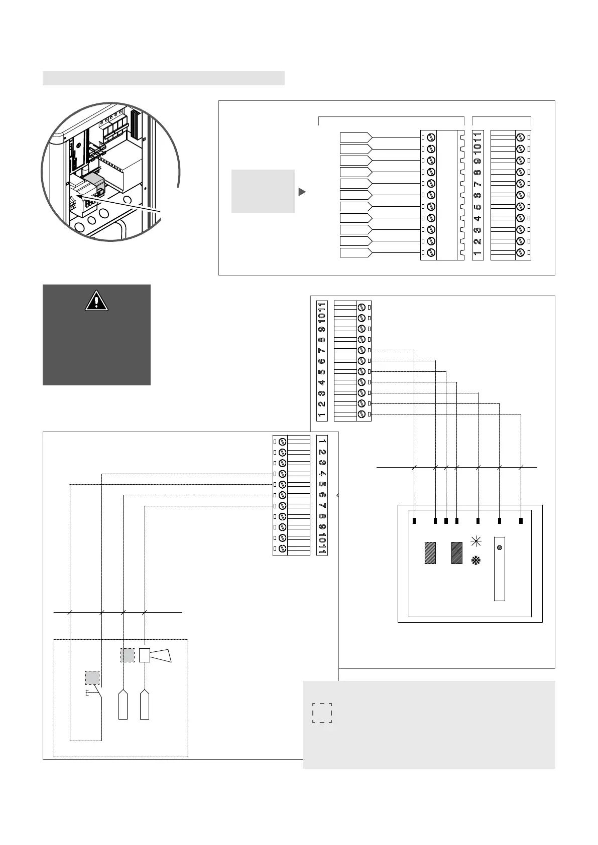
NB: for any other details, refer to the complete electric diagram on
the machine.
Key:
the auxiliary control board points highlighted are the ones that
the installer can use.
IA Auxiliary switch
AE External alarm
Indicative
position of
the auxiliary
terminal
board
on the
electrical
panel
accessory
auxiliary
control board
(11 pole)
Part connected to the system Removable part
Terminals 6 and 7 provide
basic insulation opposed
to main power supply line,
all others give a reinforced
insulation