28 18.01. 6755441_03
ANL-ANLH 020-202
EN
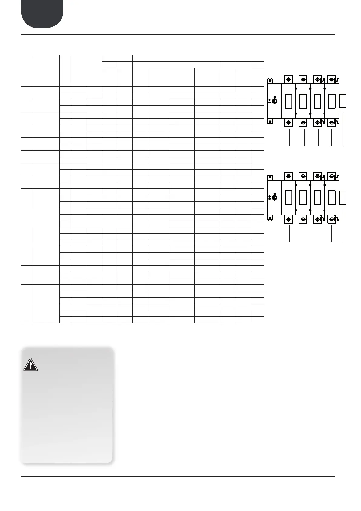
6. ELECTRICAL DATA
[n°]
Fans [n°]
TOTAL INPUT RECOMMENDED CABLE CROSS SECTION
L.R.A. F.L.A. SEZ. A SEZ. B EARTH IL
[A] [A]
[n°]
[mm
2
]
[n°]
[mm
2
] [mm
2
] [A]
020
230V/1/50Hz
° 1 1 59,5 16,5 1 1 4 2 0,5 4 25
P 1 1 26,5 17,5 1 1 4 2 0,5 4 25
025
230V/1/50Hz
° 1 1 62,5 16,5 1 1 4 2 0,5 4 25
P 1 1 63,5 17,5 1 1 4 2 0,5 4 25
030
230V/1/50Hz
° 1 1 83,7 19,7 1 1 6 2 0,5 6 25
P 1 1 84,7 20,7 1 1 6 2 0,5 6 25
040
230V/1/50Hz
° 1 1 98,7 23,7 1 1 6 2 0,5 6 32
P 1 1 99,7 24,7 1 1 6 2 0,5 6 32
020
400V/3N/50Hz
° 1 1 26,5 6,0 3+N 1 2,5 4 0,5 2,5 16
P 1 1 27,5 7,0 3+N 1 2,5 4 0,5 2,5 16
025
400V/3N/50Hz
° 1 1 32,5 6,0 3+N 1 2,5 4 0,5 2,5 16
P 1 1 33,5 7,0 3+N 1 2,5 4 0,5 2,5 16
030
400V/3N/50Hz
° 1 1 35,7 6,7 3+N 1 2,5 4 0,5 2,5 16
P 1 1 36,7 7,7 3+N 1 2,5 4 0,5 2,5 16
040
400V/3N/50Hz
° 1 1 48,7 8,7 3+N 1 2,5 4 0,5 2,5 16
P 1 1 49,7 9,7 3+N 1 2,5 4 0,5 2,5 16
050
400V/3N/50Hz
° 1 2 65,3 11,3 3+N 1 4 4 0,5 4 16
P 1 2 67,3 13,3 3+N 1 4 4 0,5 4 16
1 2 68,0 14,0 3+N 1 4 4 0,5 4 16
070
400V/3N/50Hz
° 1 2 75,3 13,5 3+N 1 4 4 0,5 4 16
P 1 2 77,3 15,5 3+N 1 4 4 0,5 4 16
1 2 78,0 16,2 3+N 1 4 4 0,5 4 16
080
400V/3N/50Hz
° 1 2 102,3 16,3 3+N 1 6 4 0,5 6 25
P 1 2 104,3 18,3 3+N 1 6 4 0,5 6 25
1 2 105,0 19,0 3+N 1 6 4 0,5 6 25
090
400V/3N/50Hz
° 1 2 96,3 17,3 3+N 1 6 4 0,5 6 25
P 1 2 98,3 19,3 3+N 1 6 4 0,5 6 25
1 2 99,0 20,0 3+N 1 6 4 0,5 6 25
100
400V/3N/50Hz
° 2 2 76,0 22,0 3+N 1 10 4 0,5 10 25
P 2 2 77,4 23,4 3+N 1 10 4 0,5 10 25
2 2 78,8 24,8 3+N 1 10 4 0,5 10 25
150
400V/3N/50Hz
° 2 2 87,0 26,0 3+N 1 16 4 0,5 16 45
P 2 2 89,8 28,8 3+N 1 16 4 0,5 16 45
2 2 90,5 29,5 3+N 1 16 4 0,5 16 45
200
400V/3N/50Hz
° 2 2 117,0 34,0 3+N 1 16 4 0,5 16 45
P 2 2 119,8 36,8 3+N 1 16 4 0,5 16 45
2 2 120,5 37,5 3+N 1 16 4 0,5 16 45
LEGEND
F.L.I.: Maximum power input
F.L.A.: Maximum current input
L.R.A.: Starting current
Sez A: Power supply connection
3+N: 3 phase + Neutral
Sez B: Control and safeties connection
EARTH: Earth connection to the unit
IL: Main isolator
L1
L2 L3 N
PE
400V/3N/50Hz
L1
N
PE
230/1/50Hz
7. ELECTRICAL POWER SUPPLY CONNECTIONS
1. Beforemakingtheelectricalconneconsensure
that the isolator is open.
2. Open the front control panel.
3. Use the holes provided in the lower part of the
cabinet for the electrical power supply and for
otherexternalwiringconnecons.
4. Enter cables into the control panel only through
the apertures provided.
5. Avoid direct contact with un-insulated copper
tubes and compressors.
6. Idenfytheterminalsforelectricalconnecon
with reference to the wiring diagram provided
loose with the unit.
7. Take the power cable into the control panel and
connect to terminals U-N and PE with respect to
(U) phase, (N) neutral, (PE) earth in the case of
singlephaseunits(230V/50Hz),
8. U-V-W for phases, N for neutral and PE for earth
inthecaseofthreephaseunits(400V/3N/50Hz).
9. Replacetheinspeconpanels.
10. Ensurethatallproteconremovedfortheelec-
tricalconneconarereplacedbeforepowering
the unit.
11. Place the main isolator (external to the unit) to
“ON”.
WARNING
It is reminded that for units of this
series, if requested by the Aermec
client or the legal owner and only on
ITALIAN territory, free start-up is pro-
vided by the regional Aermec techni-
cal assistance service. The start-up
must be previously agreed based on
theintendedmeofcompleonof
installaon.Beforethestart-upall
the works (electrical and hydraulic
connecons,llingandvenngofair
in the system) must be completed.