C
cynthia94Aug 15, 2025
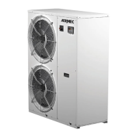
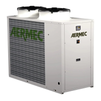
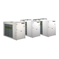
What to do if the AERMEC Heat Pump compressor stops due to the intervention of the protections?
- MMr. Riley BakerAug 15, 2025
If your AERMEC Heat Pump compressor stops due to the intervention of the protections, it could be due to several reasons. It may be caused by excessive flow pressure, low intake pressure, low power supply voltage, badly tightened electrical connections, or operation outside operating limits. Check the operating limits using the graphics. Another cause may be a malfunctioning pressure switch, which would need to be replaced. Also, check the power supply voltage and calibrations and the electrical isolation of the windings if there is a circuit breaker protection intervention. Finally, check the water flow rate if the flow switch intervention.