32
INSTALLAZIONE
•
INSTALLATION
WIRING CONNECTIONS
The unit is completely factory wired and during start-up it
only requires a power supply in conformance with the spe-
cifications on the serial plate of the unit, and fitted with ade-
quate line protection. All the connections must respect the
local legislation in force at the time of the installation.
The diagrams given in the following documentation must
only be used as a guideline for the layout of the power lines.
For specific installation requirements, refer to the wiring dia-
gram supplied with the unit.
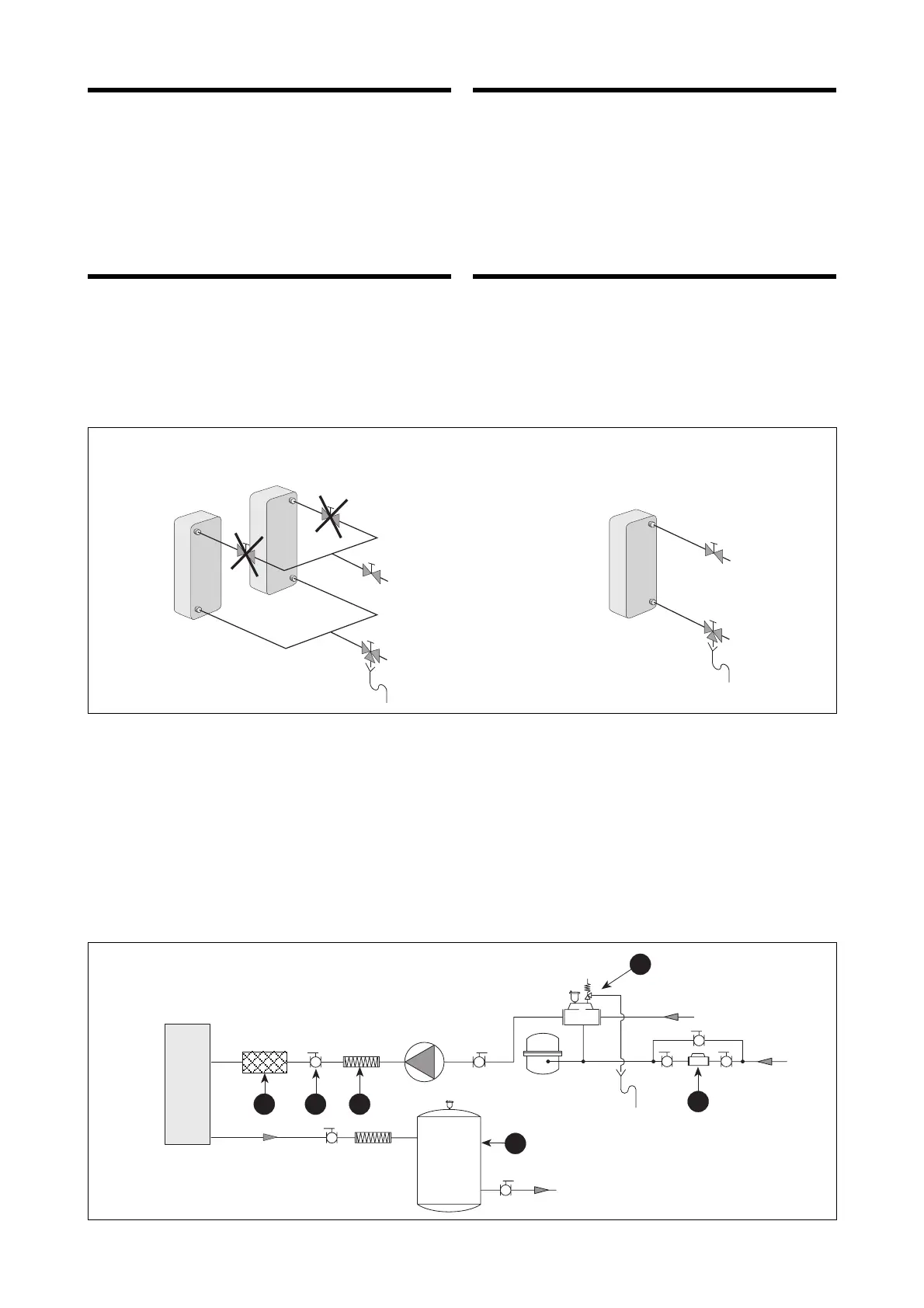
WATER CIRCUIT
The water flow to the evaporator must always be constant.
IMPORTANT: in the case of evaporators in parallel, the
water connections must be made according to the instruc-
tions given in diagram below. This layout gives a correct
balance of the flows to each evaporator.
It is strictly prohibited to mount cut-off valves on the single
evaporators, disrespect of this condition will invalidate the
warranty.
The positions and diameters of the water couplings are
given in “Dimensions”.
The following installation accessories are recommended for
evaporators and for desuperheaters:
– Inertial storage tank to alleviate the temperature difference
of the water when the compressors are stopped (1);
– high pressure flexible connectors to avoid vibration tran-
smission along the piping of the installation (2);
– manual cut-off valves between the unit and the rest of the
installation, to aid maintenance and avoid draining the
whole installation (3);
– vent valve with safety valve (4);
– automatic feeder group with gauge (5);
– antivibration feet fixed to the floor, particularly when
COLLEGAMENTI ELETTRICI
L'unità è completamente cablata in fabbrica e per la messa
in funzione necessita dell'alimentazione elettrica secondo
le indicazione sulla targhetta caratteristica dell'unità, inter-
cettata con delle protezioni in linea.
Tutti i collegamenti elettrici devono essere rispondenti alle
norme legislative locali vigenti al momento dell'installazione.
Gli schemi riportati nella seguente documentazione devono
essere utilizzati solo come ausilio per la predisposizione
delle linee elettriche. Per le necessità di installazione, fare
riferimento allo schema elettrico fornito con l'apparecchio.
CIRCUITO IDRAULICO
La portata d'acqua inviata all'evaporatore deve essere
costante in ogni momento. ATTENZIONE: nel caso di eva-
poratori in parallelo, per l’allacciamento idraulico si segua-
no le indicazioni riportate nello schema riportato di seguito.
La disposizione indicata permette un corretto bilanciamento
delle portate da inviare agli evaporatori.
Si fa obbligo, inoltre, pena il decadimento della garanzia, di
non inserire organi di intercettazione sui singoli evaporatori.
La posizione ed il diametro degli attacchi idraulici sono
riportati in "Dati dimensionali".
Si consiglia l'installazione dei seguenti accessori d'impianto
sia per gli evaporatori sia per i desurriscaldatori:
– serbatoio di accumulo inerziale per attenuare il salto di
temperatura sull'acqua quando i compressori sono spen-
ti(1);
– giunti flessibili ad alta pressione per evitare la trasmissio-
ne di vibrazioni alle tubazioni dell’impianto (2);
– valvole manuali d’intercettazione tra l'unità ed il resto
dell'impianto, per facilitare le operazioni di manutenzio-
ne ed evitare di scaricare tutto l’impianto (3);
– separatore d’aria con valvola di sicurezza (4);
– alimentatore automatico d’impianto con manometro (5);
COLLEGAMENTO IDRAULICO CONSIGLIATO
RECOMMENDED WATER CONNECTIONS
 Loading...