12 21.01 5723611_01
3 UNIT DESCRIPTION
This unit, which may only be installed outdoors, is designed and built for the air
conditioning of industrial buildings and/or processes, through the use of water or
a mixture of water and glycol within the limits that will be indicated further on in
this manual.
The units use the R32 refrigerant gas and have scroll compressors t on anti-vibra-
tion supports and are acoustically isolated by a compressor compartment. The axial
ow fans are designed to reduce sound emissions. All the models in the series are
provided without pumps or storage tanks, but other congurations are available
as options (for more details consult the dedicated technical documentation or the
selection programme available online at www.aermec.com
All the electrical connections are inside the machine, which is fully wired. The power
supply is three-phase 400V ~ 3N 50Hz with magnet circuit breakers.
All of the machine's control and adjustment components are controlled and man-
aged from the control panel integrated into the unit.
It is also possible to manage the machine using voltage-free contacts (refer to the
wiring diagram supplied with the machine).
SAFETY AND ADJUSTMENT DEVICES
The safety and adjustment of the unit on the cooling circuit is obtained with the
following devices:
— High pressure switch with manual reset
— With xed calibration, placed on the high pressure side of the refrigerant circuit,
it shuts down compressor operation in the case of abnormal operating pressure;
— Low pressure transducer
— Placed on the low pressure side of the refrigerant circuit, it communicates to
the control card the operating pressure, sending a pre-alarm in case of abnor-
mal pressure;
— High pressure transducer
— Placed on the high pressure side of the refrigerant circuit, it communicates to
the control card the operating pressure, sending a pre-alarm in case of abnor-
mal pressure;
— Leak detector located inside the compressor compartment;
— Probes for detecting the water delivery and return temperature;
— Water ow switch;
— Air drain valve
— Water lter;
the safety devices must be replaced by the AERMEC S.p.A. Technical
Service, only using original components, refer to the spare parts cat-
alogue.
IT IS FORBIDDEN: to operate the unit outside of its operating range and
with inoperative safety devices
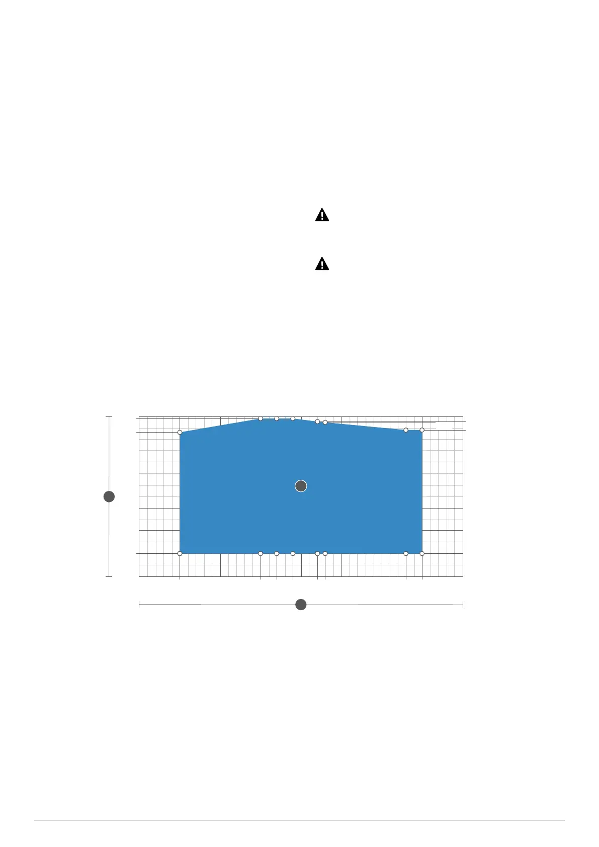
OPERATING LIMITS
In their standard conguration, the units are not suitable for installation in salty
environments.
The values shown in the table relate to the min. and max. unit temperature limits.
For more information, refer to the tables of yields and absorption dierent from
nominal, valid for ∆T = 5°C.
Operating limits - cooling mode
Version A 151-201-281-302-332-552-602
Key
A Outdoor air temperature (°C)
B Water produced (°C)
1 Standard mode
-20
-10
0
10
20
30
43
49
47,9
44
-15 -10 -5 0 2 4 5 7 8 10 15 2018 25
47,6
A
1