30 21.01 5723611_01
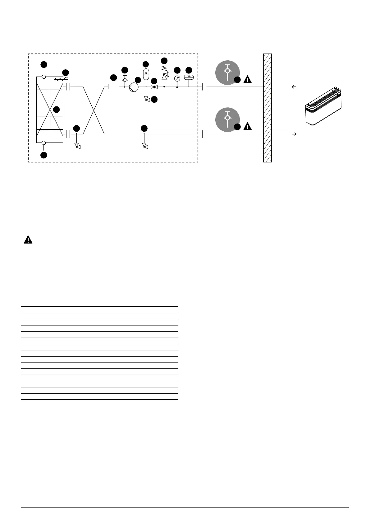
With pumps
P1-P3-I1-I3
Components as standard
1 Plate heat exchanger
2 Water temperature sensors (IN/OUT)
3 Antifreeze electric heater
4 Water lter
5 Air drain valve
6 Pump
7 Expansion vessel
8 Drain valve
9 Flow shut-o valves
10 Pressure relief valve
11 Pressure gauge
12 Flow switch
Components not provided and responsibility of the installer
13 Air drain valve (MUST BE INSTALLED IN A WELL VENTILATED LOCATION
OUTSIDE)
3
1
2
2
13
13
88
4
5
10
11
8
12
6
7
9
The drawings are provided solely as examples.
In particular, the unit is intended to be connected: to a hydronic system
that must be designed to be classied according to EN 378-1 as an indirect
ventilated system (ref EN 378-1; 2016, par. 5.5.2.2 ), as an indirect vented
closed system (ref EN 378-1;2016, par. 5.5.2.3 ), or as a double indirect sys-
tem according to EN 378-1 (ref. EN 378-1; 2016, par. 5.5.2.4 ).
■ Do not ll up the hydraulic system by glycol near the suction of the pump. High
concentration of glycol could stuck the pump. Do not use the pump to mix water
and glycol.
Water characteristics
System: Chiller with plate heat exchanger
PH 7,5 - 9
Total hardness 4,5 - 8,5 °dH
Temperature < 65 °C
Oxygen content < 0,1 ppm
Max. glycol amount 50 %
Phosphates (PO) < 2ppm
Manganese (Mn) < 0,05 ppm
Iron (Fe) < 0,3 ppm
Alkalinity (HCO) 70 - 300 ppm
Chloride ions (Cl-) < 50 ppm
Sulphate ions (SO) < 50 ppm
Sulphide ion (S) None
Ammonium ions (NH) None
Silica (SiO) < 30 ppm