52
IVEDITI 1707 - 4880981_01
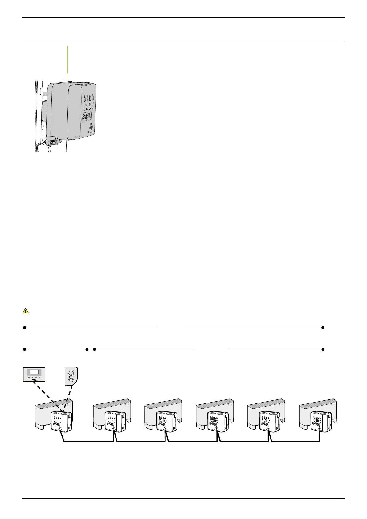
• E18 thermostat board inserted in a protec-
tive case, easily applicable to the fancoil
side.
The E1 thermostat board is complete with
protection fuse, dip-switch for configura-
tion and connectors for connection with:
• electric power supply,
• earth connection,
• valve control,
• Inverter control module power supply,
• room air temperature probe,
• water temperature probe,
• auxiliary water temperature probe,
• occupancy sensor,
• external contact,
• microswitch contact connected to fancoil
serial device,
VMF-E1 allows you to manage:
• The three fan speeds manually.
• Continuous and thermostated ventilation
through valve controls.
motor based on the load.
• Season display.
• Alarms and ventilation request display.
• One electric heater activation.
• Germicidal lamp.
• Plasmacluster filter.
• One air temperature probe.
• One water temperature probe with mini-
mum and maximum temperature and chan-
geover function.
• One additional water probe to control the
• Season changeover based on water or air
• Input for “external contact”. This is a digital
input with the following logic:
- “Open” the thermostat operates normally;
- “Closed” the fancoil is switched off.
• Microswitch for louver contact.
• Anti-freeze function.
• Occupancy sensor to enable the “SLEEP”
set-point reduction by 2 or 5 degrees,
depending on settings, in case of room not
• Input for local serial device. The E18 ther-
mostat was designed to communicate
with other E0 and/or E1 and/or E18 type
thermostats, through a dedicated serial
connection based on TTL logic standards.
The above serial communication is essen-
tial for the exchange of information within
thermostats and with max length of about
the small areas with multiple fancoils that,
however, are to be controlled from a single
control point. Specifically in this network
there is always a master to which the user
which controls the operation of the slaves
connected to it, based on the settings made
on its user interface.
• Supervision serial connection input. In the
networks composed of more fancoils divi-
ded into independent climate zones, the
VMF-E18 zone regulator allows communi-
cation with a system central supervision
CONTROL PANELS ACCESSORIES, THERMOSTATS AND VMF SYSTEM CONTROL DEVICES
-
TTL NETWORK
• Max length of TTL line 30m.
The Master fan coils are equipped with control
panel and electronic board with microprocessor,
equipped with outputs for insertion in a TTL
network.
The Slave fan coils are equipped with electronic
All TTL network fan coils must have the same type
of accessories.
The units connected to the TTL network are auto
-
matically recognised, they do not require any
TTL Line
Max 30m
+
-
FCXI + VMF-E18
FCXI + VMF-E18
+
VMF-E4 / VMF-E2
MASTER
SLAVE
VMF-E2
VMF-E18 VMF-E18
VMF-E18 VMF-E18 VMF-E18 VMF-E18
E4
VMF-E4