WT-9 Dynamic Club S FLIGHT MANUAL Section 7 Page 7-10
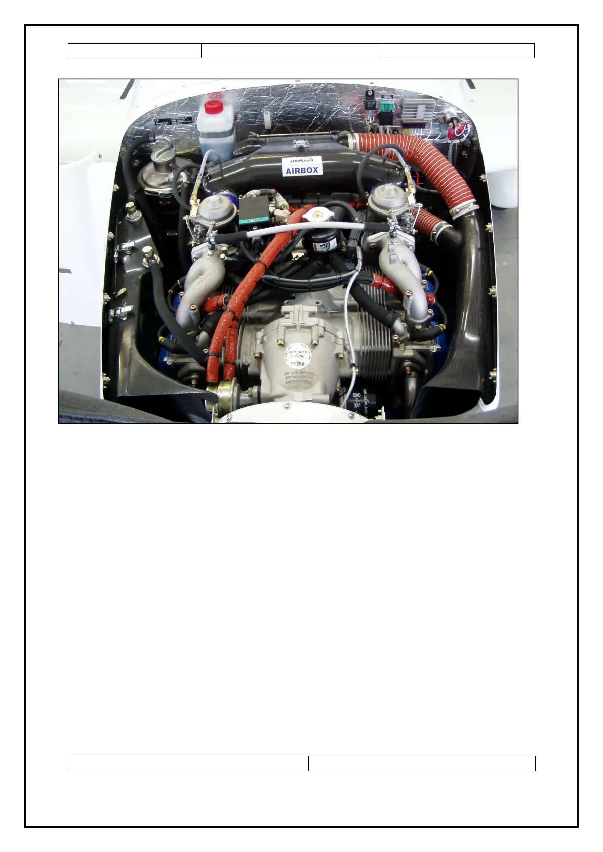
Fig. 13 Powerplant ROTAX 912 ULS
1 – Coolant filler tank 5 – Carburettor 9 – Oil radiator
2 – Regulator 6 – Ignition
3 – Oil tank 7 – Coolant overflow bottle
4 – Air filter 8 – Cabin venting intake
7.10 Fuel system
The fuel tanks are located in the forward box of the wing central panel. The auxiliary
tanks are installed in the wings. The fuel system scheme is shown at fig.14.
The fuel is fed from the fuel tank into the fuel cock located inside the cockpit below
the instrument panel, then through the fuel filter into the engine fuel pump into the
carburettor. The unconsumed fuel is supplied back through return piping into the left
tank. The vent pipe is outgoing from the upper part of the fuel tank, proceeds along
the fire wall and the vent opening is located at a lower surface of the fuselage behind
the fire wall. The electrical fuel indicator switch allows the indication of the fuel
quantity in the left or the right fuel tank. Red light annunciator above the fuel
indicator will be illuminated when 7 litres of fuel remain in each fuel tank.
Date: 01.10.2006 / Rev.: 3
3
4
5
5
6
7
8
9
2
1