12
Testing Fiber Links
Step I - Set the Reference (One Jumper Method)
Figure 3-2 illustrates the following procedures.
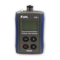
1 Turn on the CSM1 optical power meter and CSS1 light source. Allow the CSS1 light source to
stabilize (minimum of 2 minutes).
2 Set both instruments to the desired test wavelength.
3 Select the appropriate ber optic transmit and receive test jumpers. The ber type of these
jumpers must match the ber type of the link to be tested.
4 Wrap and secure the transmit jumper ve times around the appropriate diameter mandrel.
Note: Clean both ends of the transmit jumper.
5 Connect the transmit jumper to the CSS1 output port.
6 Mount an adapter cap on the CSM1 that matches the free connector on the transmit jumper.
7 Connect the free end of the transmit jumper to the CSM1. If necessary, press the [dB/dBm]
key to display optical power in [dBm].
8 If measured output power is outside of the normal range (specied by manufacturer), clean
all ber connections or replace the transmit jumper. Repeat steps 5 - 7.
9 To set the reference level at the current wavelength perform the following steps:

 Loading...