16
Step III - Measure Link Insertion Loss
Figure 3-4 illustrates the following procedures.
18 Connect the free ends of the transmit and receive jumpers to the link under test.
Note: Clean jumper end that connects to patch panel prior to every test.
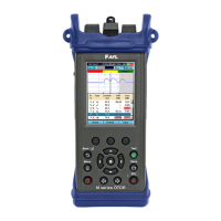
19 CSM1 will measure and display the insertion loss of the link under test.
20 Record link insertion loss at the current test wavelength.
21 Repeat steps 18-20 for all links to be tested at the current wavelength.
 Loading...