10
5 Electrical Connection
Notes:
1. Electrical installation & maintenance shall be conducted by licensed electrician and shall comply with
local Wiring Rules.
2. After the inverter has been installed in its fixed position, the electrical connection to the unit can be
established.
3. Make sure Max. Open Voltage and short-circuit current of the each PV strings accord with the Spec.
4. Choose the appropriate cable width for AC/DC wire. The cross sectional area of DC input conductor lead
should be 4mm
2
PV wire, that of AC output conductor should also be 4mm
2
cooper wire, and that of
external ground conductor should be 4mm
2
cooper wire.
5. On both sides of inverter to the grid and PV array, there must be between circuit breaker and surge
protector, and during inverter electrical connections, circuit breakers on both sides should be
disconnected to prevent electric shock.
6. Before connecting the inverter to PV arrays and public grid, make sure the polarity is correct.
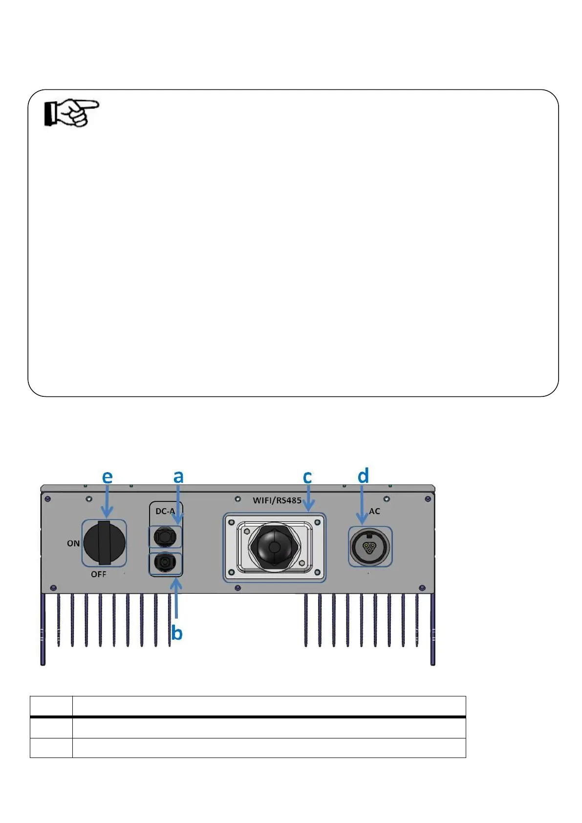
5.1 Overview of the Connection Area
The following figures show the assignment of the individual connection areas on the bottom of the inverter.
Anyhome Series (Single MPPT Tracker): HNSxxxxTL-1(xxxx=1000,1500,2000,2500,3000,3600)
DC connectors ( + ) for connecting the PV strings
DC connectors ( − ) for connecting the PV strings
 Loading...