OPERATOR’S MANUAL
19
SFA-32
There are some important items to observe when preparing to install the precision flow
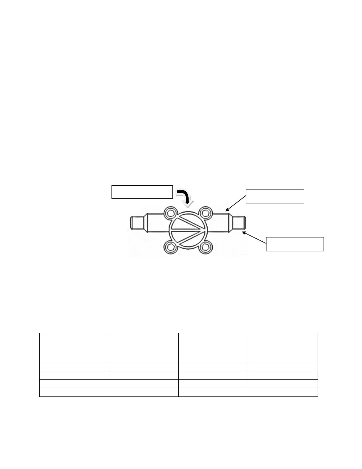
meters. On both the inlet and outlet end of the flow meter there are two different sized
hose barbs. The smaller is designed to use ¼” ID hose, and the larger barb closer to the
center of the meter is designed to accept 3/8” ID hose. The first step in installing the flow
meters is determining which barb will work best to adapt to the size and type of
plumbing on the planter/applicator. The flow meters are supplied with two 2” pieces of
¼” tubing plus 2 clamps. The tubing is provided as a way to easily transition to the
existing plumbing. If the planter/applicator uses 3/8” hose in the system, you can simply
slide it on and clamp it to the flow meter on the larger barb.
Another important feature of the flow meter is a directional arrow showing how material
should flow through the meter. The directional indicator arrow is stamped into the
housing on the opposite side of where the cable goes into the meter. It is very critical
that the flow meters are installed accordingly. Inaccurate or inconsistent readings will
occur if they are installed backwards.
Each of our 4 different precision flow meters has a different operating range so it is
important that they be chosen correctly for your application. Physically – the meters are
identical. You will be able to identify which flow meter you have by the tagged part
number on the meter cable. Below is a chart showing the operating specifications of
each flow meter.
Flow Meter
Specifications:
Part Number