OPERATOR’S MANUAL
18
SFA-32
FLOW METER INSTALLATION
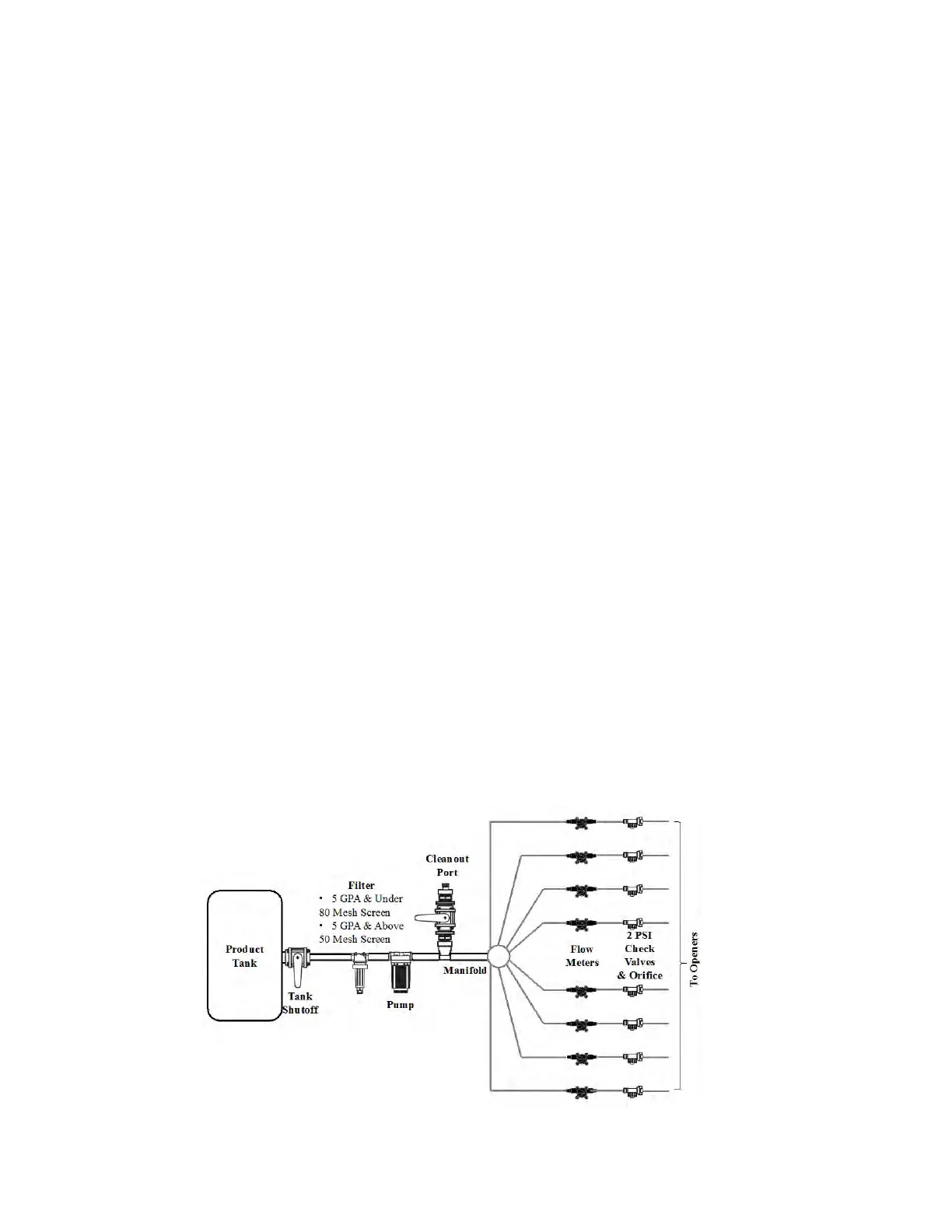
A plumbing diagram for a typical system used on a planter for the pop up/side by side fertilizer
has been included. Starting with the product tank that is normally mounted on the planter frame
each of the components used in the system will be discussed regarding their function and
installation.
#1 Leading out of the tank a main shutoff valve should be in place to cut product flow to the
entire system.
#2 The next component on the diagram is a filter which is critical for keeping foreign material out
of the pumping system that would cause plugs or blockages to occur. It is recommended for an
application rate of 5 gallons per acre or less to use an 80 mesh filter screen. Application rates
higher than 5 gallons per acre can be applied with a 50 mesh screen filter. A finer screen is used
at lower application rates to keep the small flow meters from plugging. The filter should be
placed before the pump to allow for proper filtering of the fertilizer being applied.
#3 The pump is the next item in line after the filter. There are many types of pumps that are
commonly used for liquid fertilizer application. Piston, squeeze, hydraulic and 12V DC type
pumps have all been used with this system. All these pumps work well as long as they are
properly sized for the specific application rate that is being applied.
#4 After the pump a cleanout port is shown that would be used for rinsing out the system after
the season is over. It may also be used for rinsing if you are going to be out of the field and will
not be using the system for an extended period of time. The cleanout port will also be useful in
flushing out the system if blockages should occur due to contamination problems in the fertilizer
system. The clean out port consists of a valve and a garden hose adapter for hooking up the
rinsing system.
#5 Following the cleanout port is the distribution manifold followed by the individual row flow
meters. The flow meters can be grouped together after the manifold or distributed on the bar
individually closer to each opener.
#6 An optional bracket (Part No. AE6675) is available for purchase that holds up to 8 flow meters.
This will help keep track of which flow meter is going to which row plus it helps in making a neat,
safe, and organized installation of the flow meters. Each precision flow meter is made with 2 sizes
of hose barbs on each end of the flow meter housing. These barbs are ¼” and 3/8” which makes
adapting to your planter plumbing system easy.
#7 After the flow meters a check valve/orifice plate assembly is recommended. A 2 psi check
valve works well for most systems. The lines will stay filled with liquid and leakage on the ends will
be prevented when the unit is raised. Properly sized orifice plates will make the application rate
accurate and consistent from row to row.
 Loading...