11. AGA Module Gas Hob - Freestanding Installation
The appliance must have an anti-tip device correctly installed
as per these instructions (Fig. 11.1) and (Fig. 11.2). If you
pull the appliance out from the wall for any reason, make
sure that the device is properly engaged when you push the
appliance back against the wall. If it is not, there is a possible
risk of the appliance tipping over and causing injury if you or
a child stand, sit or lean on an open door.
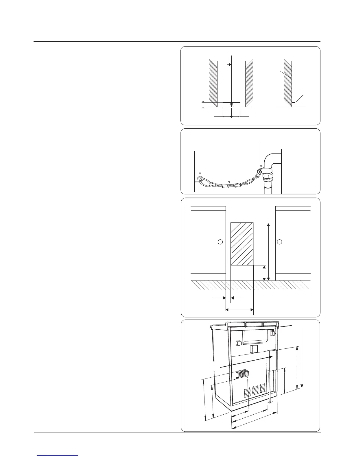
To reduce the risk of tipping, the range must be secured
by a properly installed anti-tip bracket supplied with the
appliance. The bracket must be tted within the shaded area
shown in the diagram (Fig. 11.1) using 2 x screws (No. 10 x 1
¼”) tted in the wall or oor, longer screws may be required
depending on the wall or oor covering, also when a exible
hose is used, a chain restraint must be used as illustrated (Fig.
11.2).
For an appliance other than an upright appliance, which may
be connected with a hose assembly, the supply connection
point must be accessible with the appliance installed (Fig.
11.3) and (Fig. 11.4).
IMPORTANT: The gas supply connection at the wall MUST
NOT project out from the wall by more than 45mm, so that it
does not foul with the back of the appliance (Fig. 11.3).
Gas Connection
CAUTION: ENSURE THAT THE APPLIANCE IS
ISOLATED FROM ELECTRIC SUPPLY
The appliance can be installed with an approved exible
connection. Supply piping should not be less than ⁄ I/D.
Connection is made to the ½”BSP female threaded elbow
located just below the hotplate level on the near left hand
side of the appliance.
To conrm the pressure setting, follow the “Pressure testing”
page 30 procedure.
Fig. 11.1