20
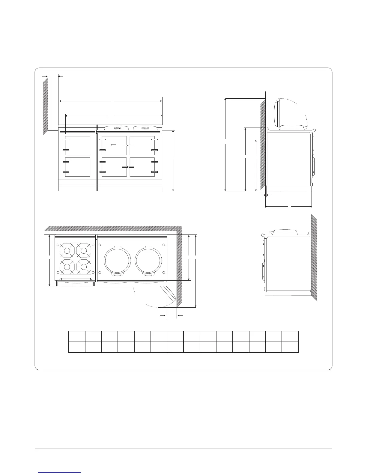
Specifications
E
POSITION OF LIDS
WHEN RAISED
**N
c
**O
H
M
K
J
B
K
A
D
G
OVEN DOOR IN
OPEN POSITION
PLAN VIEW
DESN 516395 A
Fig. 10.1
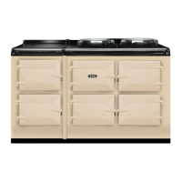
AGA Total Control (TC3) / Dual Control (DC3) with TC/DC Gas Hob Module (TC3M/DC3M)
A B C D E G H J K L M **N **O
mm 1589 951 913 680 60 1388 760 1145 116 10 698 1533 800
NOTE: When surveying for the installation the actual clearance required for the ‘body’ of the appliance should be increased
overall by 10 mm beyond the gures quote above. This allows safe margin to take into account the natural dimensional
variations found in major castings in particular the width across an appliance recess could be critical.
** POSITION FOR GAS SUPPLY PIPE TO MODULE