26
13. Gas connection Integrated Module
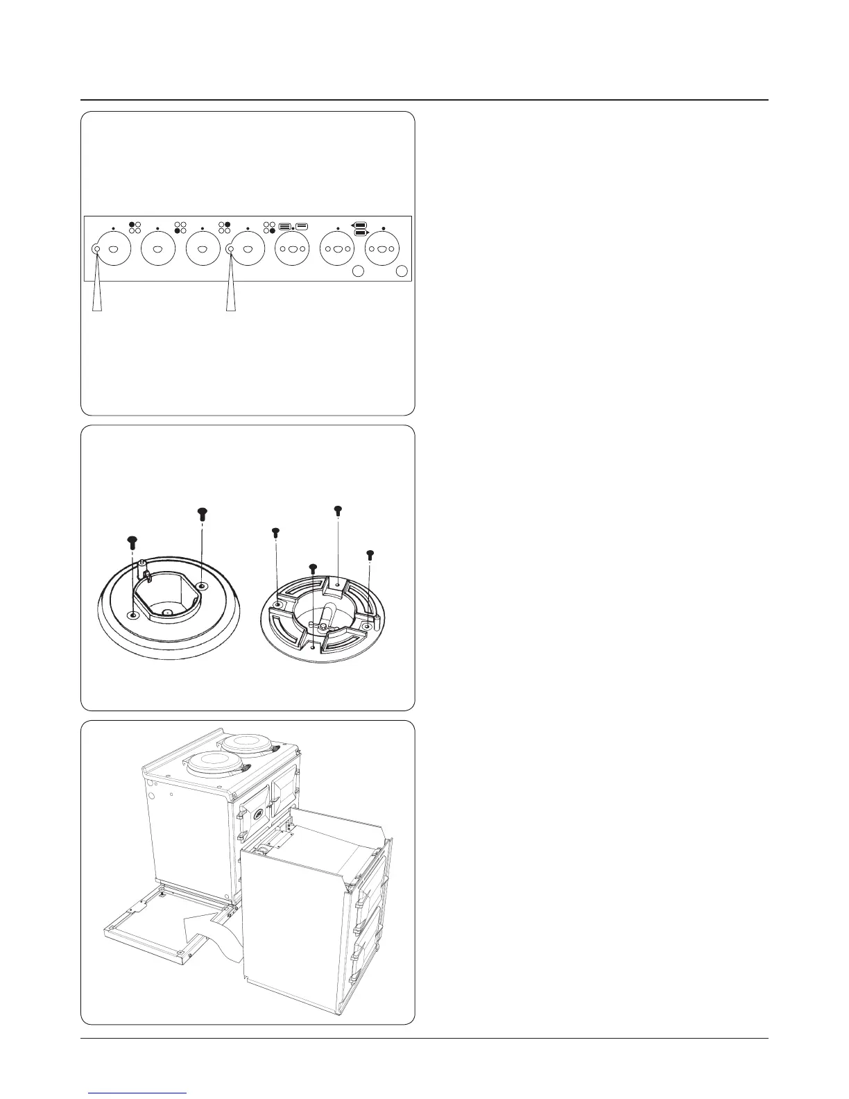
1. Prior to electrical connections, remove top plate
assembly from Module as follows:-
A. Remove pan supports and all controls knobs.
B. Remove four chrome buttons and the four top plate
retaining screws (2 each side).
C. Remove two screws from control panel (one from
left hand hole and one from centre hole). (See Fig.
13.1).
D. Pull top plate forward slightly and lift up at front.
Support top plate and disconnect wiring to the two
neons. Remove top plate.
E. Lay the top plate on its top face, suitably protected.
2. Remove hotplate as follows:-
A. Remove burner heads and burner caps.
B. Remove all of the screws retaining hotplate burner
trims (4 from Wok burner, 2 each from the other
three burners). (See Fig. 13.2).
C. Carefully remove burner trims and gaskets, taking
care not to damage gaskets or burner electrodes.
D. Disconnect earth wire from left hand control panel
mounting bracket.
E. Remove hotplate casting.
3. Check power to the appliance is o and isolated.
4. Connect the mains wire to the terminal block at the rear
of the appliance (See Electrical Connections).
5. Slide Module and plinth until rear tongue bracket
engages fully into rear of base slot. (See Fig. 13.3).
Ensure the appliance is aligned squarely with the plinth
then proceed to engage the front tongue bracket
into the slot on the underside of the base plate. Once
satised that the front tongue bracket is engaged fully
lock into place by tightening the two M6 screws fully.
6. Check to ensure that the Module front plate and AGA
Total/Dual Control front plate are the same height,
and that the overlap strips correspond correctly. If not,
adjustment should be made to the relevant appliance,
at this stage.
DESN 516280
REMOVE 2 FIXING SCREWS
DESN 517426
Fig. 13.1
DESN 511646
(WOK BURNER ONLY)
Fig. 13.2
Fig. 13.3