23
DESN 516883
DESN 516880
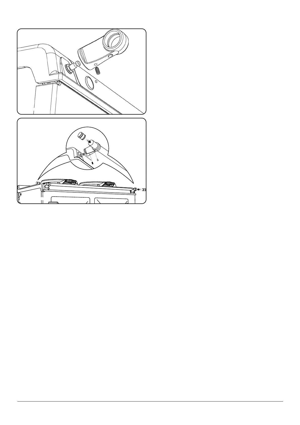
Fig. 14.2
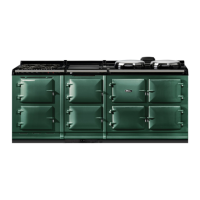
Fig. 14.3
Fitting the Handrail
1. Fit the handrail bracket over the xing stud located on
the top plate. Lock into position by tightening the grub
screw nearest the appliance Fig. 14.2.
2. Slide the handrail through the handrail brackets Fig.
14.3.
3. Once the handrail assembly is located squarely, lock the
handrail in position by winding in the grub screws on
the underside of each handrail bracket.
4. Once the handrails are locked in position, t the
handrail endcaps. The endcaps should be carefully
pushed into place until they sit ush with the outside
face of each bracket (a light smear of lubricant such as,
hand or dish soap on the end cap ‘O’ rings may ease
tment Fig. 14.3.
5. Finally, t the plinth facia to the magnets on the front
of the plinth. Make sure that the plinth facia is centrally
located and does not overhang the range.
6. Commission the AGA R7, as stated in the relevant
Installation Instructions and carry out functional test on
each of the features of the AGA R7.
7. Attach warning hanger (EGLL516660) located in
literature pack, to AGA R7 handrail when installation is
complete. Advise customer to remove and read warning
label.
8. Hand this Guide to the user for retention and instruct in
the safe operation of the appliance.
9. Also advise the user that, for continued ecient and
safe operation of the appliance, servicing is carried out
at intervals recommended by the AGA distributor.