Chapter 6: Replacing Assemblies
To remove and replace the acquisition board assembly
6–22
To remove and replace the acquisition board assembly
Use this procedure to remove and replace the acquisition assembly. When necessary, refer to
other removal procedures.
1 Disconnect the power cable and remove the cover.
2 Remove the Probe Interface subpanel assembly.
3 Remove the hex nuts that secure the BNC connectors to the front panel.
Use a 9/16” nut-driver to remove the hex nuts. See page 6–11.
4 Disconnect the three or four SMB cables from J13, J14, J15, and J16 from the
Acquisition assembly.
These cables are located behind the Aux Trigger Input BNC connector. See page 6–12.
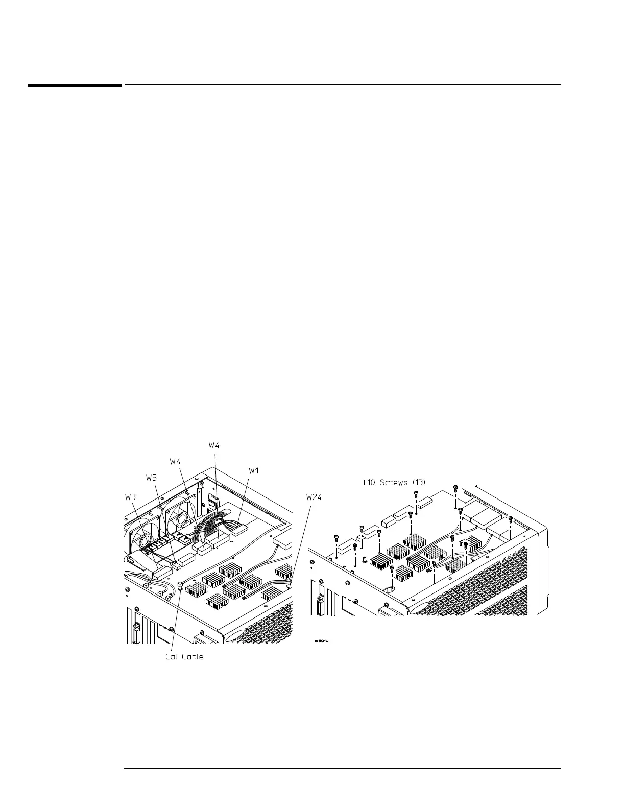
5 Disconnect the following cables from the inside edge of the Acquisition assembly:
• Power supply sense cable W1
• Probe control cable W17
• Power harness cable W4
• Line sync cable W5
• Acquisition cable W3
• Internal digital cable W24 (MSO model oscilloscopes only)
These cables are attached to J5, J150, J6, J7, J9, J10, and J18 connectors. The J18 connector is
near the CH4 attenuator.
6 Remove the twelve Torx T10 screws that secure the acquisition board to the chassis,
then lift the board back from the front panel until the BNC connectors clear the panel.
Lift the board away from the chassis.
Figure 6-21
Removing the Acquisition Assembly
 Loading...


