Chapter 6: Replacing Assemblies
To remove and replace the oscilloscope graphics board and display board
6–25
To remove and replace the oscilloscope graphics board and display board
Use these steps to remove and replace the oscilloscope interface board and display board. When
necessary, refer to other removal procedures.
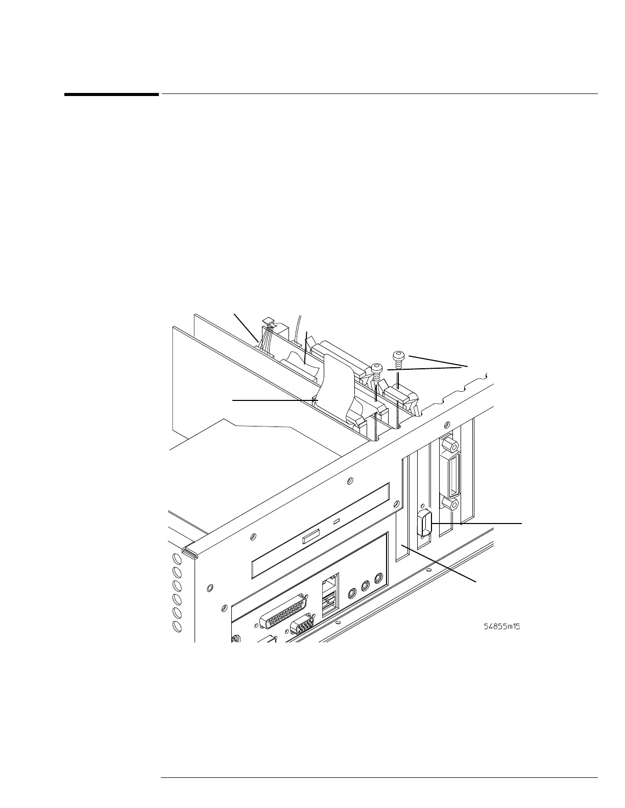
1 Disconnect the power cable and remove the cover.
2 Disconnect these cables from the display board:
•Bridge cable W22
• Backlight primary cable W21
• Display video cable W11
3 Remove the two Torx T10 screws that secure the oscilloscope interface and display
boards to the chassis.
These screws are at the rear of the chassis.
Figure 6-24
Removing the Oscilloscope Interface and Display Boards
4 Grasp the graphics board at the top corners and pull the board straight up until it is
free of the card cage.
5 Grasp the display board at the top corners and pull the board straight up until it is free
of the card cage.
6 To replace the oscilloscope graphics and display boards, reverse the above procedure.
Be sure to observe correct polarity on all cables when replacing the boards.
W21
W11
W22
Display Board
Graphics Board
T10 Torx Screws
 Loading...


