Troubleshooting 79
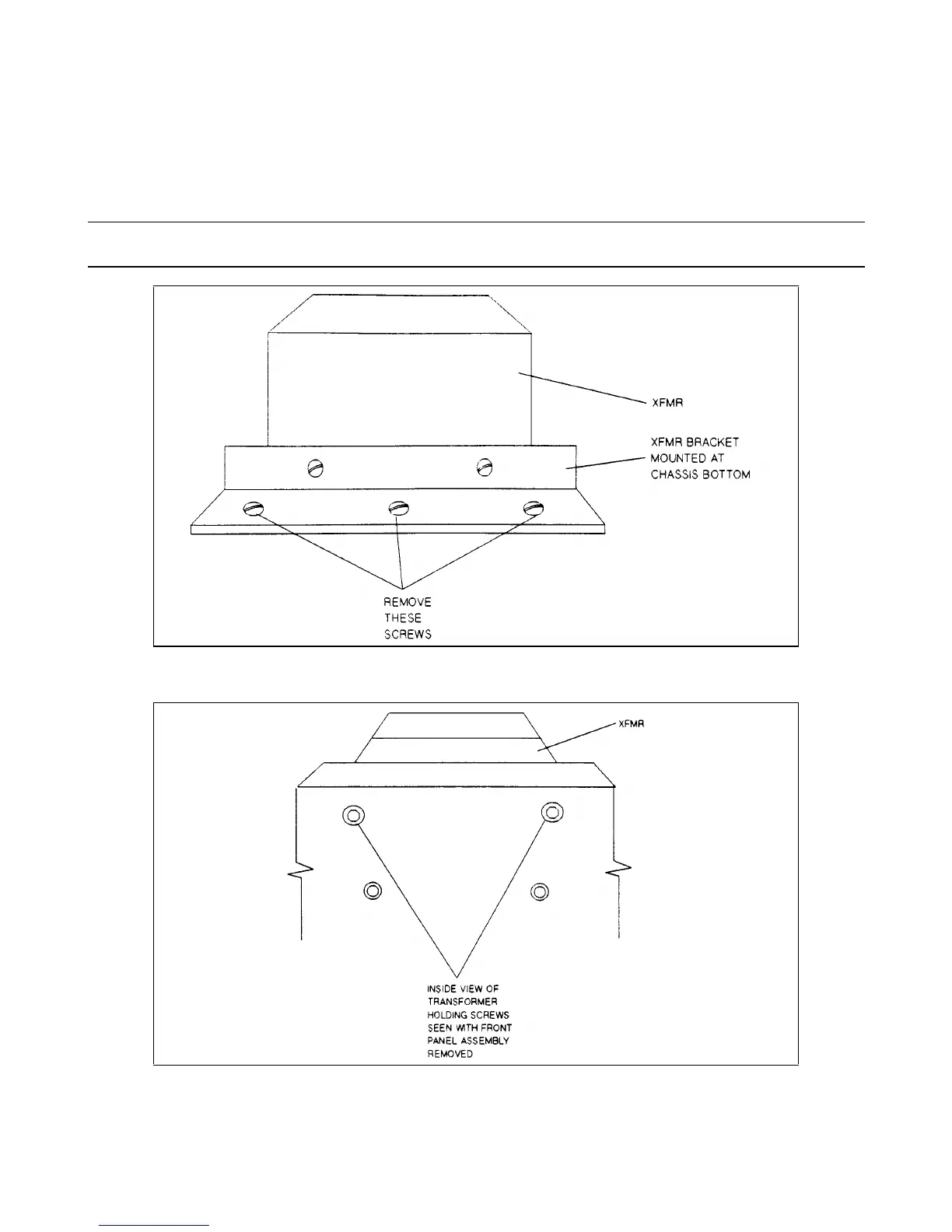
a. In the supply chassis, remove the two screws (three screws for 6x4xA) securing the transformer to the bottom of the
chassis.
b. At the front of the chassis, remove the two screws securing the transformer to the chassis.
c. Use long nose pliers to disconnect all wires going to the transformer terminals.
d. Lift the transformer out of the chassis.
Note The AC power connections at the transformer secondary are model dependent. Be sure to note the color
code of the wires and the respective terminals the wires connect to for subsequent reconnection.
Figure 3-23. Location of XFMR Holding Bracket at Bottom of Chassis
Figure 3-24. Location of XFMR Holding Screws, Inside View
 Loading...


