Principles of Operation 89
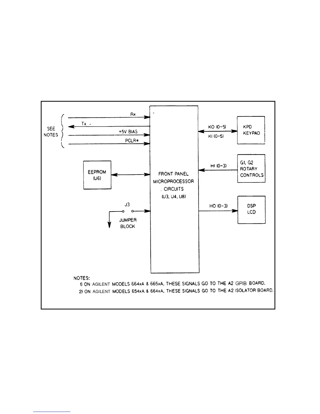
A3 Front Panel Board Circuits (Figure 4-5)
The supply’s front panel assembly contains a circuit board, a keypad, a liquid crystal display (LCD), and rotary controls
(A3G1 and A3G2) for the output voltage and current. The on/off switch, not shown in Figure 4-5, is also located on the
front panel. The same front panel board is used in all Agilent models.
The front panel board (A3) contains microprocessor circuits (microprocessor and ROM chips), which decode and execute
all keypad commands which are transferred to the power supply output, via the serial I/O port to the A2 board (GAL chip
and isolators), and to the secondary interface circuits on the A1 main board. The front panel microprocessor circuits also
process power supply measurement and status data received on the serial I/O port. This data is displayed on the LCD.
Figure 4-5. Front Panel Board, Simplified Block Diagram
The EEPROM (electrically erasable programmable read-only memory) chip on the front panel board stores a variety of data
and configuration information. This information includes calibration constants, GPIB address, present programming
language, and model-dependent data, such as the minimum and maximum values of voltage and current. one of the
EEPROM storage locations holds a checksum value which is used to verify the integrity of the EEPROM data.
All Agilent models can be calibrated from the front panel. Agilent models 664xA and 665xA can also be calibrated via the
GPIB by using SPCI commands (see Appendix A in the Operating Manual). Access to the calibration data in the EEPROM
 Loading...


