76 Troubleshooting
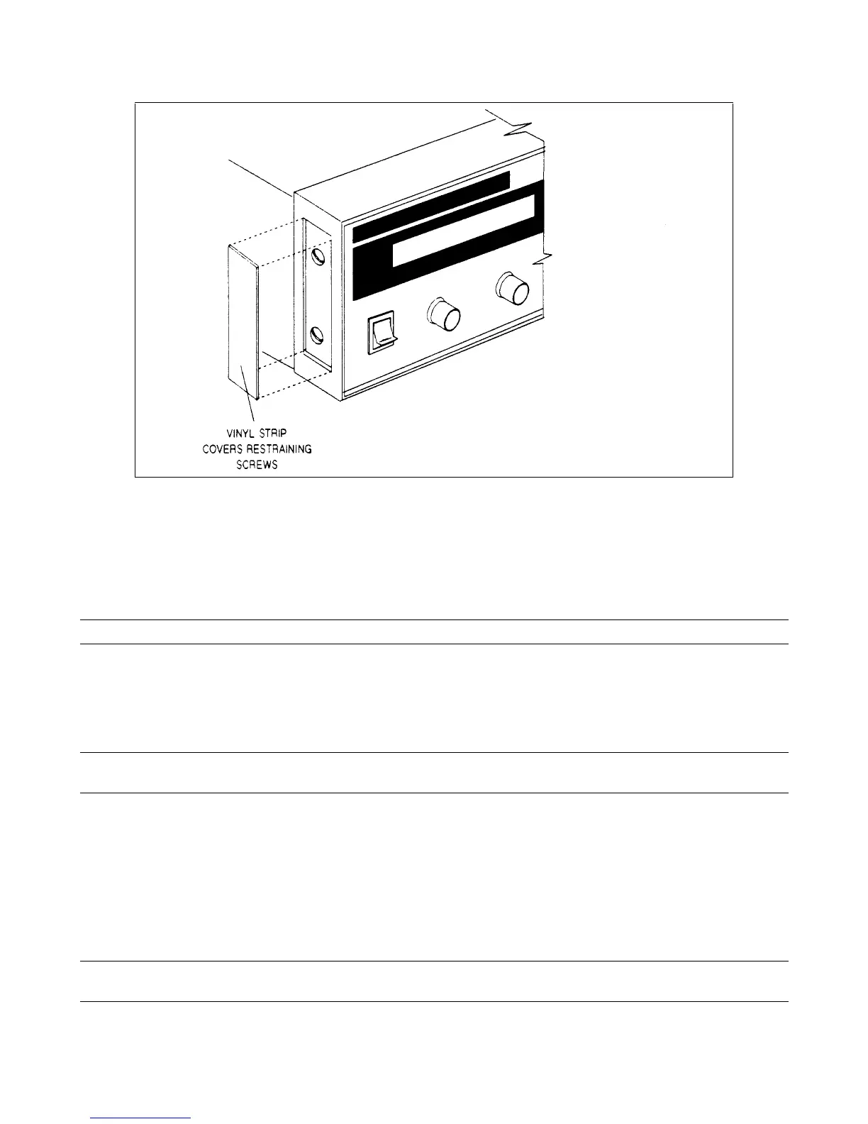
Figure 3-21. Removing Vinyl Strip from Sides of Front Panel Assembly
S1 Line Switch, Removal and Replacement
a. First remove the front panel assembly as described under, "Front Panel Assembly, Removal and Replacement”.
b. On the front panel assembly, release the switch locking tabs by pressing them inward against the body of the switch,
and then remove the switch.
Note When re-installing this switch be sure that the screened letter "O" is at the top of the switch.
A3 Front Panel Board, Removal and Replacement
First remove the front panel assembly as described under, “Front Panel Assembly, Removal and Replacement”. Once you
have access to the front panel board perform these steps:
Note Be careful not to unscrew the knob set screws too far out as they can easily fall out of the knob and
become lost.
a. Use a small allen wrench (0.050") to loosen the set screws inset in the knobs. Remove knobs and shaft bushings.
b. Remove the holding screw (if installed) that secures the board to the front panel assembly. The screw is located near J4
on the front panel board.
c. In order to remove the board itself from the assembly you must slide the board to the left to disengage the holding clips.
To do this, first lift up the restraining tab on the circuit board and then slide the board to the left and lift it out.
d. Disconnect display ribbon connector J2. (The other end of this cable goes to the display panel. DO NOT remove cable
at display end.)
Note When reinstalling the front panel board, be sure to line up the “stripe” of the ribbon cable with pin 1 on
J2.
 Loading...


