34 Troubleshooting
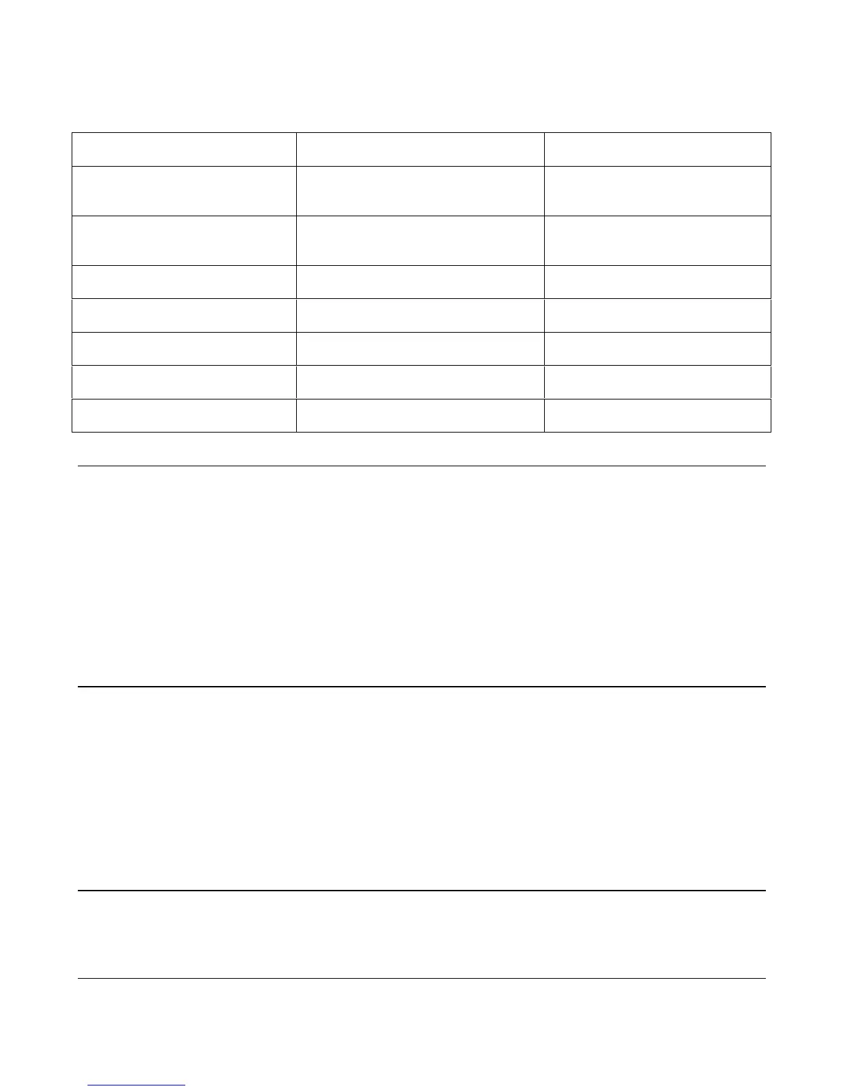
Table 3-1 Test Equipment Required for Troubleshooting
Type Purpose Recommended Model
GPIB Controller (used only with
models 664xA & 665xA).
To communicate with the supply via the
GPIB interface.
HP Series 200/300
Signature Analyzer To troubleshoot most of the primary and
secondary interface circuits
Agilent 5005 A/B
Digital Voltmeter To check various voltage levels. Agilent 3458A
Logic Probe To check data lines. Agilent 545A
Oscilloscope To check wave forms and signal levels. Agilent 54504A/54111A
IC Test Clips To access IC pins. AP Products No. LTC
Ammeter/Current Shunt To measure output current.
Overall Troubleshooting
Overall troubleshooting procedures for the power supply are given in the flow chart of Figure 3-2. The procedures first
check that neither an AC input, nor a bias supply failure is causing the problem and that the supply passes the turn-on self
test (no error messages). The normal turn-on, self-test indications are described in the "Power-on Checkout" paragraph in
Chapter 3 of the Operating Manual.
If the supply passes the self test, Figure 3-2 directs you to perform the verification procedures in Chapter 2 from the front
panel to determine if any functions are not calibrated or are not operating properly. For models 664xA & 665xA, the
verification tests will also check to see if the supply can be programmed from a GPIB controller. If the supply fails any of
the tests, you are directed to the applicable troubleshooting procedure or flow chart. Signature analysis (SA) is used to
troubleshoot some of the supply’s digital circuits.
Power-On Self-Test
The power-on, self-test sequence consists of tests of the front panel, primary GPIB interface (for 664xA & 665xA Models
only), secondary interface circuits, and the isolator board (for 654xA & 655xA models). If the supply fails the self test, the
output will remain disabled (turned off) and the front panel display should indicate the type of failure. The error will be
displayed indefinitely and the supply will not accept GPIB or front panel commands.
Note that in order to perform troubleshooting procedures that require you to program the supply, you will have to disable
the self test. You can do this by turning the supply off after it has failed the self test, and by holding down the "7" key on the
front panel for two seconds while turning the unit on. This will cause the supply to skip the power-on self test. Table 3-2
lists the self test error messages that can appear on the display and gives the probable cause for each error.
Note For models 664xA & 665xA, a partial self test is performed when the *TST? query is executed (see Table
3-2). Those tests that interfere with normal interface operation or cause the output to change are not
performed by *TST?. The return value of *TST? will be zero if all tests pass, or the error code of the first
test that failed. The supply will not display error codes and will continue to attempt normal operation if
*TST? returns a nonzero value.
 Loading...


