Troubleshooting 75
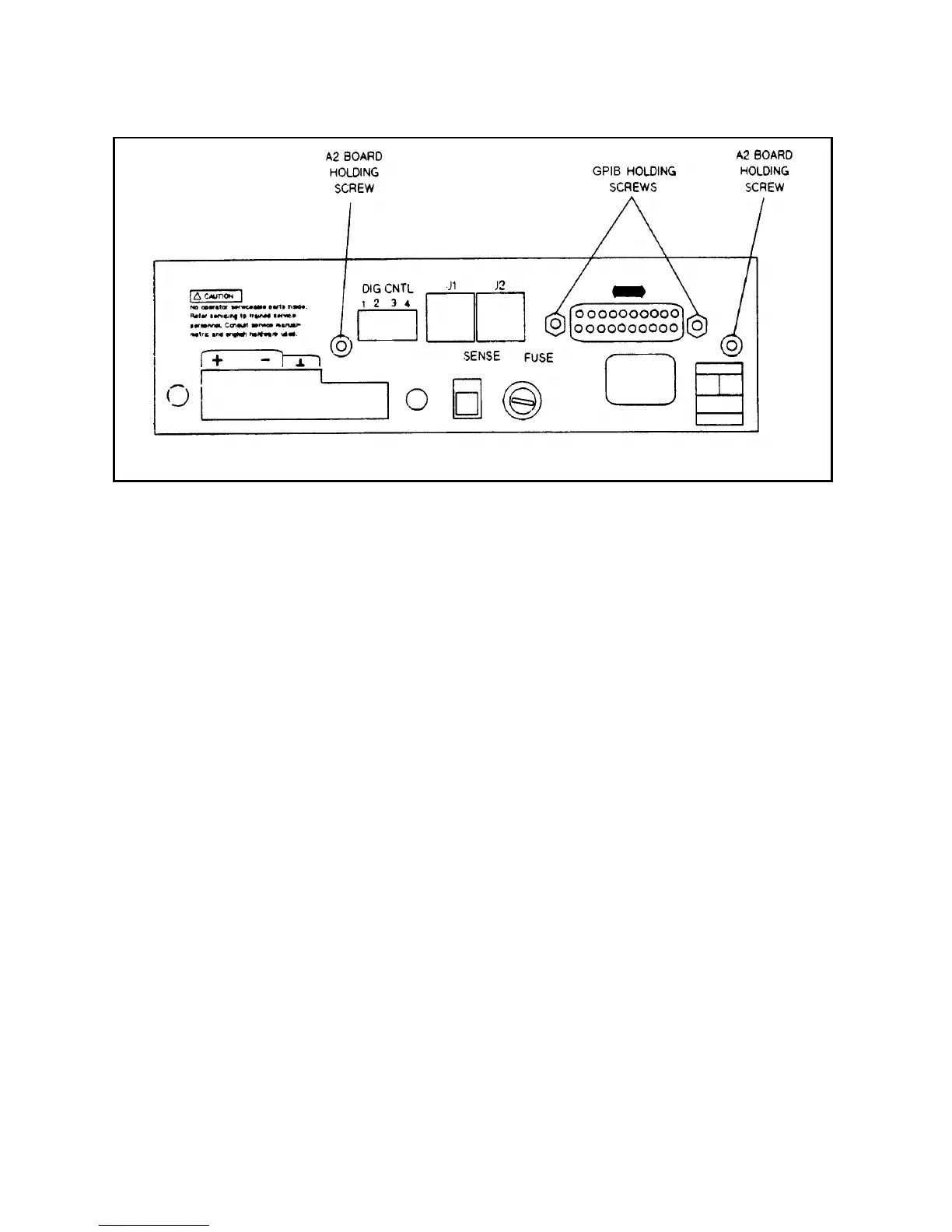
Figure 3-20. GPIB Connector and GPIB Board Holding Screws, Power Supply Rear View
A2 Isolator Board, Removal & Replacement (for 654xA & 655xA Only)
To remove the Isolator board, proceed as follows:
a. Remove the top cover of the power supply as described under, "Top Cover Removal and Replacement."
b. At the rear of the power supply, locate and remove the two (2) screws that hold the Isolator board to the chassis. You
may need to hold the nuts for these screws stationary while you unscrew the screws. The nuts are on the inside of the
chassis.
c. From the top of the power supply, disconnect the phone cable from connector J800 on the A2 board (the other end of
this cable goes to the main board).
d. Disconnect the phone cable from connector J801 on the A2 board (the other end of this cable goes to the front panel
board).
e. Disconnect connector from J803 on the A2 board (the other end of this cable goes to the transformer secondary).
f. Remove the A2 board from the power supply.
g. To reinstall the Isolator board, perform the above steps in reverse order.
Front Panel Assembly, Removal and Replacement
This procedure removes the front panel assembly from the power supply.
a. Remove the Power Supply Cover as described earlier in, "Top Cover Removal and Replacement . "
b. Locate and carefully peel off the vinyl trim (one strip on each side of front panel assembly) to gain access to the side
screws that secure the front panel assembly to the chassis.
c. Using a T10 Torx screwdriver, unscrew the screws from the side of the front panel.
d. Disconnect the phone cable from connector J6 on the A3 board (the other end of the cable goes to the A2 board).
e. Now move the front panel assembly forward a few inches away from the chassis to gain access to the S1 power switch.
f. Disconnect the wires going to the S1 switch assembly and note the color coding of the wires and the respective pins to
which they connect for subsequent reconnection.
g. The front panel assembly can now be removed from the power supply.
h. To reinstall the front panel assembly, perform the above steps in reverse order.
 Loading...


