84 Principles of Operation
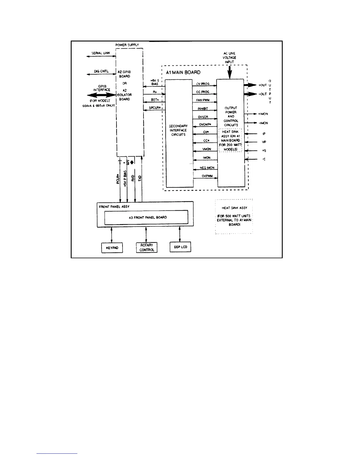
Figure 4-2. Overall Block Diagram
The CV DAC/Op amplifier converts the programmed value of voltage on the bus into the CVPROG signal, which is sent to
the CV control circuits in order to control the magnitude of the output voltage in the CV mode. The CVPROG signal is in
the 0 to -10 V range, which corresponds to the zero to full-scale output voltage range of the supply.
The CC DAC/Op amplifier converts the programmed value of current on the bus into the CCPROG signal, which is sent to
the CC control circuits in order to control the magnitude of the output current in the CC mode. The CCPROG signal is in
the 0 to -10 V range, which corresponds to the zero to full-scale output current range of the supply.
The comparator circuits, in conjunction with the readback DAC/Op amplifier, return the following signals to the
microprocessor (see Figure 4-3):
• Monitored output voltage (VMON).
• Monitored output current (IMON).
• Negative monitored output current (NEG IMON) .
• Ambient temperature (THERM AMB).
• Heat sink temperature (THERM HS).
• Programmed voltage value (CVPROG).
• Programmed current value (CCPROG).
 Loading...


