is considerably easier to use than load resistors. It
eliminates the need for connecting resistors or rheostats in
parallel to handle power, it is much more stable than a
carbon-pile load, and it makes easy work of switching
between load conditions as is required for the load
regulation and load transient response tests. Substitution of
the electronic load requires minor changes to the test
procedures in this section.
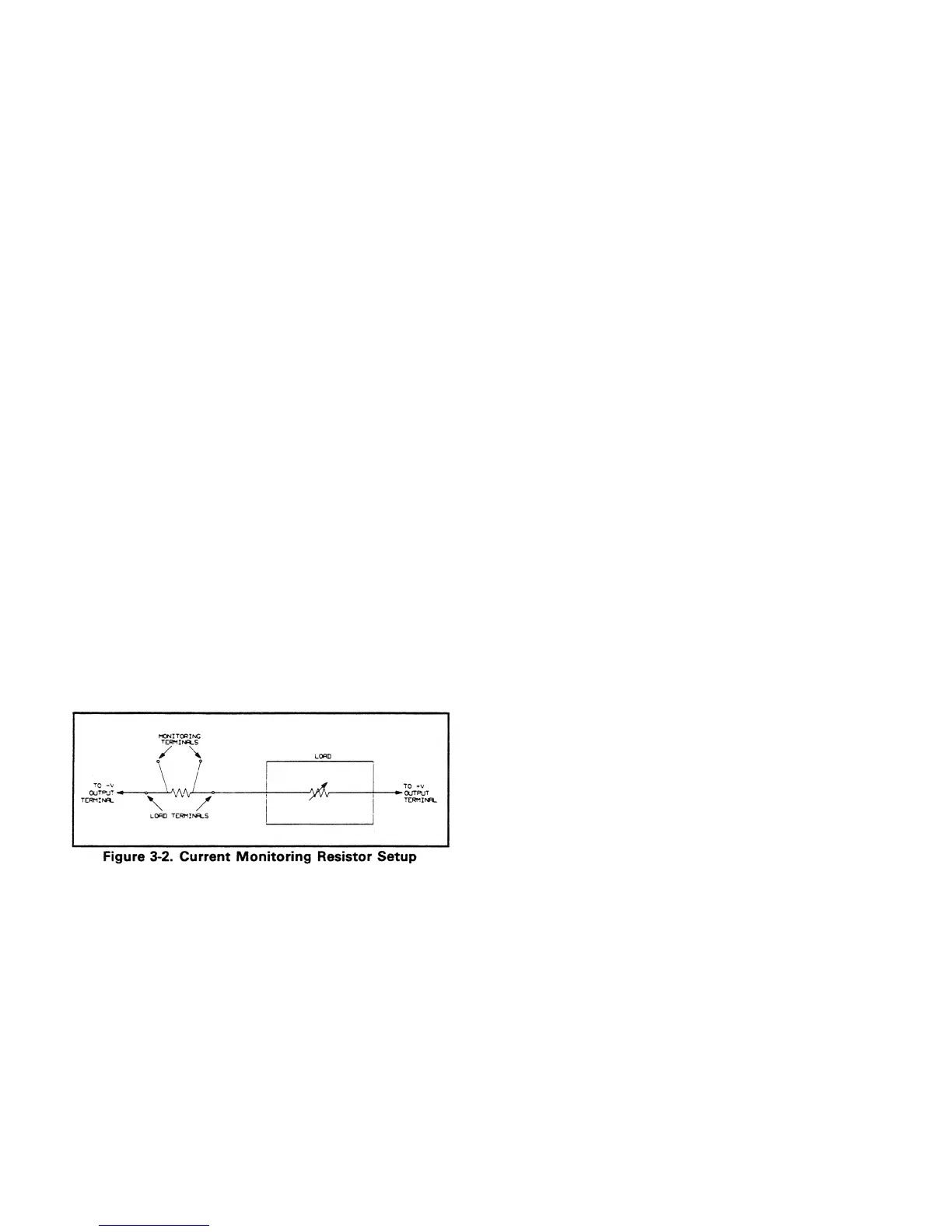
3-8 Current-Monitoring Resistor. To eliminate output
current measurement error caused by voltage drops in the
leads and connections, connect the current monitoring
resistor between the - V and the load as a four-terminal
device. Figure 3-2 shows the connections. Connect the
current-monitoring leads inside the load-lead connections
directly at the monitoring points on the resistor element.
performed using only the front panel keypad; however, an
current programming accuracy and readback accuracy tests.
The test procedures are written assuming that you know
controller or locally using the control keys and indicators on
the supply's front panel. Complete instructions on remote
and local programming are given in the Operating Manual.
NOTE
In the test programs that follow, the brackets < >
indicate a number to be sent. The < ch > specifies
the output channel number from 1 through 4. The
voltage and current values which are sent to the
specified output channel are given in Tables 3-2 and
3-3.
3-10 Constant Voltage (CV) Tests
3-11 CV Setup. If more than one meter or a meter and an
oscilloscope are used, connect each to the + S and - S
terminals by a separate pair of leads to avoid mutual
coupling effects. Connect only to + S and - S because the
unit regulates the output voltage that appears between + S
and - S, not between + V and - V. Use coaxial cable or
shielded 2-wire cable to avoid noise pickup on the test leads.
3-12 Voltage Programming and Readback Accuracy. This
and front panel display functions are within specifications.
a. Turn off the supply and connect a digital voltmeter
between the + S and - S terminals of the output to be
tested.
b. Turn on the supply and select the desired output
(OUTPUT SELECT key on the front panel).
c. Program the selected output channel to zero volts by
sending the string:
VSET < ch >, 0
d. Record the output voltage readings on the digital
voltmeter (DVM) and the front panel display. The
readings should be within the limits specified below for
the particular output type tested. Also, note that the
display indicates the output current and the CV, RMT,
and ADDR annunciators are on. Note that the output
current reading is approximately zero because there is no
load connected.
Prog. Accuracy Display Accuracy
Output (DVM Reading) (Front Panel LCD)
40WLV/80WLV 0 V ± 19mV DVM ± 25 mV
40WHV/80WHV 0 V ± 50mV DVM ± 55 mV
e. Read back the output voltage from the selected channel
10 OUTPUT 705; “VOUT? < ch > “
20 ENTER 705;A
30 DISP A
40 END
f. Record the value displayed on the controller. This value
should be within the DVM reading noted in step d and
the limits specified below.
Readback Accuracy
Output (Controller Display)
40WLV/80WLV DVM ± 20 mV
40WHV/80WHV DVM ± 50 mV
g. Program the selected output's voltage to the High Range
Full Scale value (20 V for 40WLV/80WLV or 50 V for
40WHV/80W'HV outputs) by sending the following
string:
VSET < ch >, < 20 or 50 >
h. Record the output voltage readings on the DVM and the
front panel display. The readings should be within the
limits specified below for the particular output type
tested.
Prog. Accuracy Display Accuracy
Output (DVM Reading) (Front Panel LCD)
40WLV/80WLV 20 V ± 31 mV DVM ± 35 mV
40WHV/80WHV 50 V ± 80 mV DVM ± 80 mV
i. Run the program listed in step e - Record the value
displayed by the controller. This value should be within
the limits specified below.
Readback Accuracy
Output (Controller Display)
4OWLV/80WLV DVM 30 mV
40WHV/80WHV DVM 75 mV
j. Repeat steps a through i for each output present in your
supply.
3-4
±
±
3-9 GPIB Controller. Most performance tests can be
GPIB controller is required to perform the voltage and
how to program the supply remotely from an GPIB
the GPIB by entering and running the following program:
test verifies that the voltage programming, GPIB readback,
An GPIB controller must be used for this test.
 Loading...


