120 Diagrams
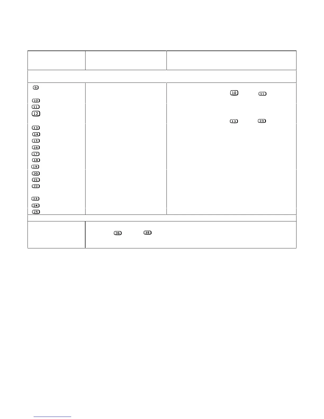
Table 6-3. Troubleshooting Test Points (continued)
TEST POINT
No. & Loc.
Signal Tested Measurement and Conditions
A4 AC Input Board
-C307 +15 Vp primary bias common Connect meter or scope common here. Then make
measurements at test points
through
.
R317 +15 Vp primary bias
+15 ± 0.9V
+C352 +26V +24.4V to +28.6V
-C315
Secondary common Move meter or scope common here. Then make
measurements at test points
through
.
R333 +5V secondary bias
+5 ± 0.2V
R331 +15V
s
secondary bias
+15 ± 0.9V
+C353 +26V +24.4V to +28.6V
R330 -15V
s
secondary bias
-15 ± 0.9V
+C354 -25V -22.5V to -27.5V
U310-6 RELAY ON* 0V
U308-6 RESET 0V
U308-7 BIAS OK +5V
U308-1 PREF +2.5V
U308-5 RESET* Held low for approximately 50 ms at power-on, then goes
high.
U311-7 FAN DETECT +3V
D317 -25V +3V
U311-2 FAN_PWN +0.6V
A3 FET Board
Note:
Test points through are on the A3 FET Board. Troubleshooting procedures at these
points are given under Dynamic Troubleshooting section of the FET Troubleshooting Chart
(Table 3-4).
 Loading...


