Troubleshooting 73
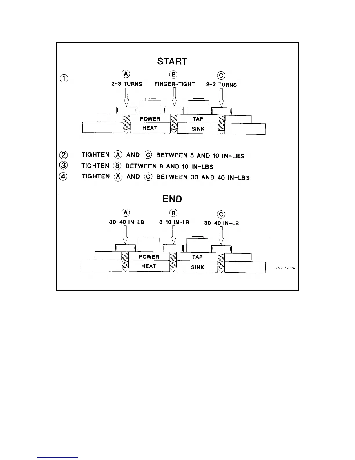
Figure 3-19. Proper Mounting Procedure for Output Rectifiers D900
A3 FET Board and Heatsink Assembly
1. Disconnect cables/wires from the following points:
a. + 15V
P
bias cable W8 from A4J400 on the AC Input Board.
b. + (red) and -(black) rail cable W9 leads from E411 and E412 on the AC Input Board;
c. 2-wire cable W7 from A3J200 on the FET Board.
2. Remove screw securing the FET heatsink to the fan assembly.
3. Remove screw securing the FET heatsink to the bottom of the main chassis.
4. Slide the FET Board/Heatsink Assembly forward and lift it out of chassis.
5. Pry up the plastic tabs securing the FET Board and the Heatsink Assembly to the metal bracket and separate the
heatsink from the bracket.
To further separate the A3 FET Board from the Heatsink Assembly, proceed as follows:
 Loading...


